4-6 888-2629-200 10/6/10
WARNING: Disconnect primary power prior to servicing.
Section 4 Theory of Operation
Maxiva ULX COFDM Series
Analog television requires an additional, faster version of ALC to correct for sync
compression/expansion effects versus average picture level. This fast ALC loop is
independent of the TCU and is handled exclusively in the analog domain. The down
converter board, located inside the transmitter cabinet (on the ceiling), generates a fast
error signal, a detected sync pulse from the cabinet or system RF output sample, which
adjusts the predriver level to negate the effects of compression or expansion due to
changing average picture level.
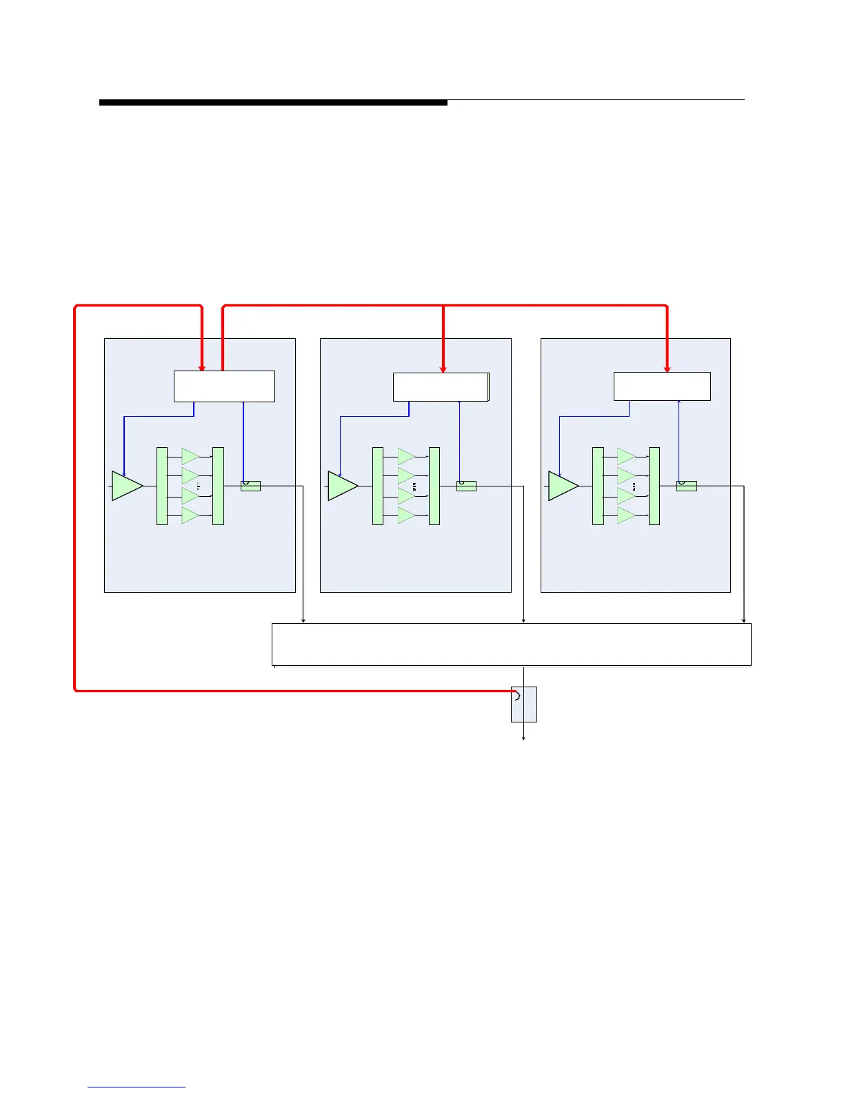
Figure 4-2 Control System Simplified Block Diagram
MAIN UCP
System Power Reference
From System Bus
S
÷
16 PAs
Cabinet 1 ALC
S
÷
16 PAs
Cabinet 2 ALC
S
÷
16 PAs
Cabinet 3 ALC
PA CAB
UCP
PA CAB
UCP
CABINET
COMBINER
Transmitter Power
Sample
(Used for power
Monitoring only. Not
used for ALC)
(Used for power raise/lower
command. Not used for ALC)
Transmitter Power Sample
From MCM
Cabinet Bus
From MCM
Cabinet Bus
From MCM
Cabinet Bus
Main TCU PA Cab TCU
PA Cab TCU
Cabinet Combiner
 Loading...

