10/6/10 888-2629-200 4-21
WARNING: Disconnect primary power prior to servicing.
Section 4 Theory of Operation
Maxiva ULX COFDM Series
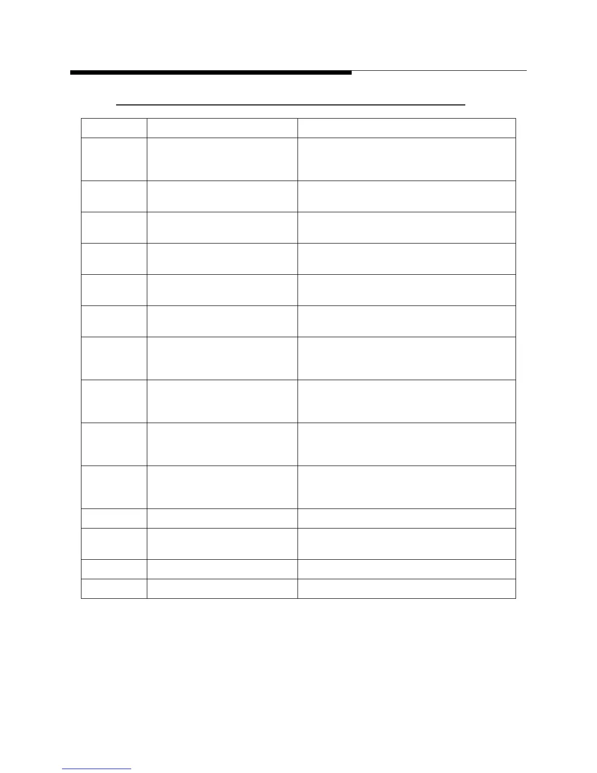
Table 4-9 AC2 MOV2 Connector J4B (25 pin stacked female dsub)
Pin Signal Description
1 /MOV_SENSE CMOS input -MOV board sense status-’0’ on
this line indicates the MOV board is present.
TVS protection. 1K pull up to +5Vdc
2 +15Vdc +15Vdc @ 200mA maximum limited by 0.2A
PTC.
3 -15Vdc -15Vdc @ 200mA maximum limited by 0.2A
PTC.
4 PH_AB_SAMPLE Analog input- AC phase AB sample sine wave
input scaled to 2Vrms=245VAC
5 PH_BC_SAMPLE Analog input- AC phase BC sample sine wave
input scaled to 2Vrms=245VAC
6 PH_AC_SAMPLE Analog input- AC phase AC sample sine wave
input scaled to 2Vrms=245VAC
7 FUSE1 Open CMOS input -MOV board sense status-’1’ on
this line indicates the fuse is ok. TVS
protection. 1M pull down
8 FUSE2 Open CMOS input -MOV board sense status-’1’ on
this line indicates the fuse is ok. TVS
protection. 1M pull down
9 FUSE3 Open CMOS input -MOV board sense status-’1’ on
this line indicates the fuse is ok. TVS
protection. 1M pull down
10 FUSE4 Open CMOS input -MOV board sense status-’1’ on
this line indicates the fuse is ok. TVS
protection. 1M pull down
11-13 NC Not connected.
14 +5Vdc +5Vdc @ 200mA maximum limited by 0.2A
PTC.
15-23 GND Ground
24-25 NC Not connected
 Loading...

