10/6/10 888-2629-200 1-9
WARNING: Disconnect primary power prior to servicing.
Section 1 Introduction
Maxiva ULX COFDM Series
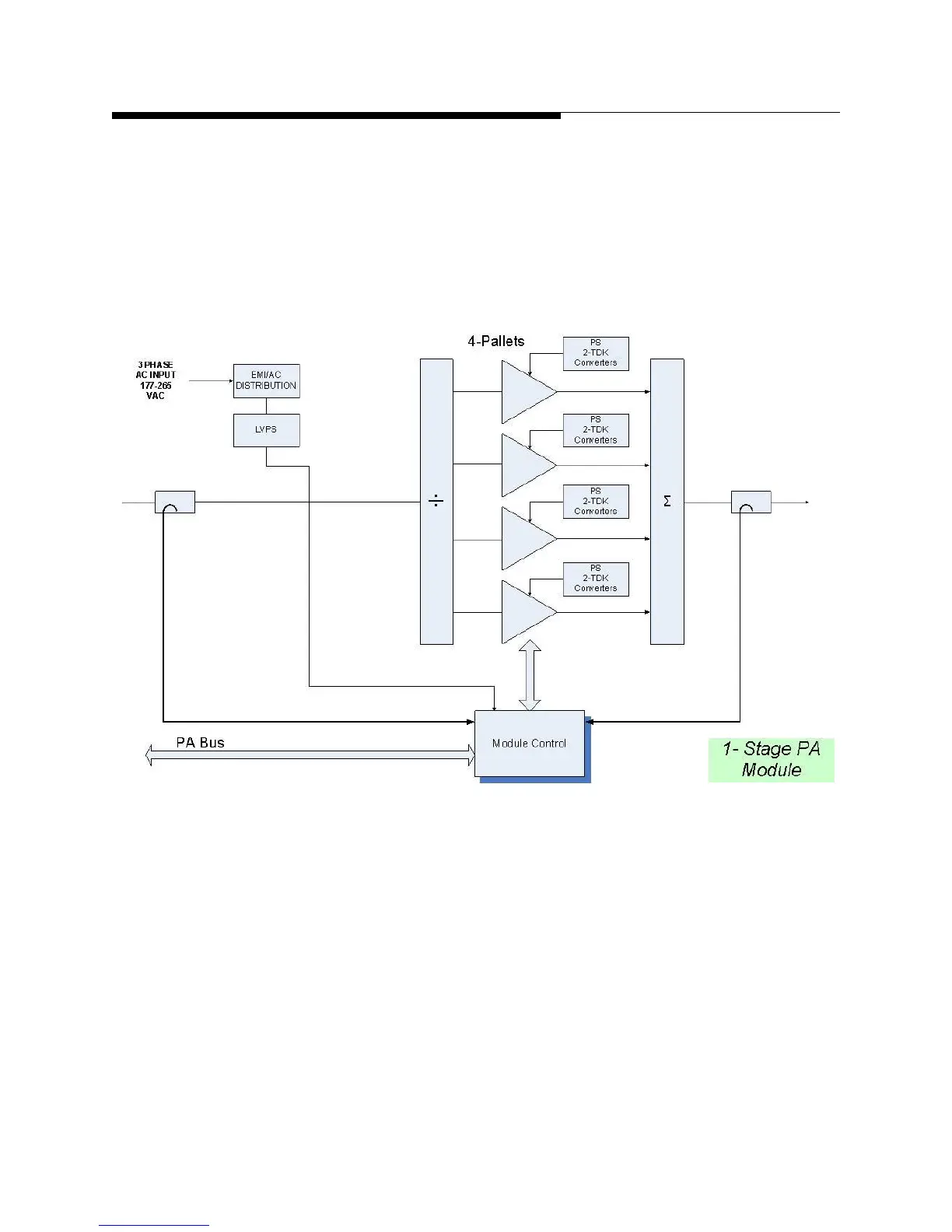
to achieve the various power levels shown in Table 1-1 page1-4. A simplified block
diagram of the PA module is shown in Figure 1-5 on page 1-9.
The amplifier and driver modules are interchangeable and do not contain
microcontrollers but instead use a CPLD based monitor board in each PA to report
faults to the TCU and to take appropriate self-protective action if needed.
Figure 1-5 PA Module Simplified Block Diagram
 Loading...

