10/6/10 888-2629-200 1-11
WARNING: Disconnect primary power prior to servicing.
Section 1 Introduction
Maxiva ULX COFDM Series
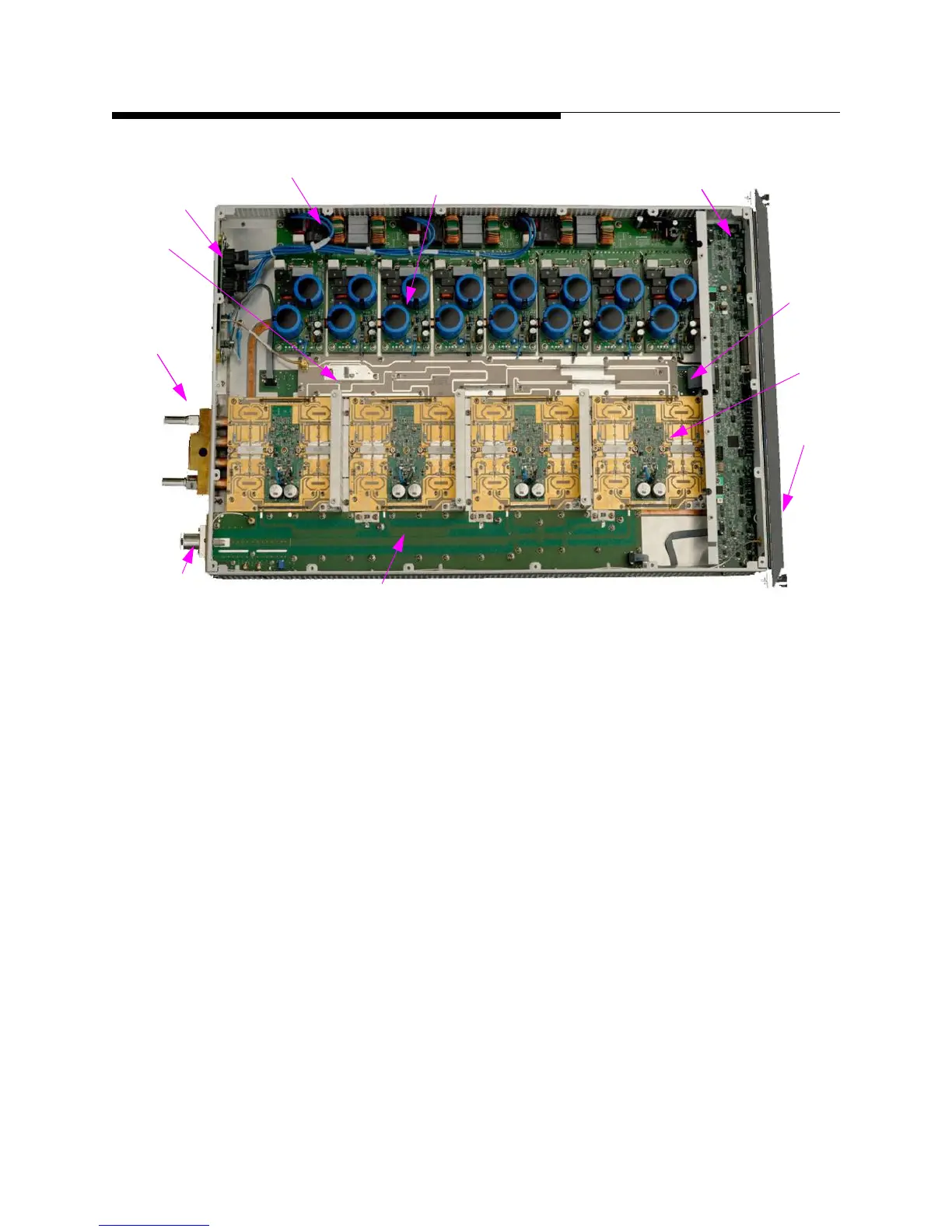
Figure 1-7 Maxiva ULX PA Module (top view, cover removed)
Each PA module consists of the following components:
a. Monitor Board - Responsible for all monitoring and protection of the module.
Reports to the transmitter TCU via the parallel control lines.
b. Connector I/O Board -I/O Connector Board provides interface connections
between PA Module and transmitter back plane. The board includes a single
hybrid connector on one side and five (5) connectors on the other side. The large
hybrid connector interfaces with mating connector on the back plane board. It
contains seven (7) AC contacts, twenty four (24) small signal contacts, and a sin
-
gle RF coaxial connector.
c. AC Distribution Board - The AC distribution board provides three phase AC to
the eight power supply boards. It also provides AC line filtering, step-start func
-
tion and transient protection for the module.
d. Power Supply Boards - The eight (8) AC/DC power supplies provide 44VDC to
50VDC power to each pair of FET’s on the four (4) PA pallets. Voltage varies
with modulation type and channel.
Coolant
In/Out
RF Out
Coolant
a
c
a
g
h
e
d
a
b
f
i
 Loading...

