1-14 888-2629-200 10/6/10
WARNING: Disconnect primary power prior to servicing.
Section 1 Introduction
Maxiva ULX COFDM Series
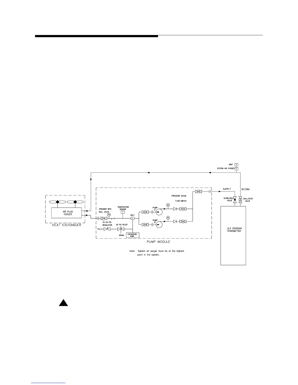
d. Supply and return line hose and fittings.
e. PCI (pump control interface) located in the TCU
f. Transmitter PA Module, Splitter and Combiner Cold Plates
The liquid cooling system is an efficient closed loop, pressurized system. Prior to
operation the cooling system must be properly prepared for operation and bled to
remove trapped air. Instructions for cooling system preparation can be found in Section
2.
The heat exchanger and pump module unit operates on either 208-240 VAC, 50/60 Hz
or 380-415 VAC 50/60 Hz. The operating voltages and frequencies should be provided
at time of order. The number of heat exchanger fans will vary with model number.
Figure 1-8 Simplified Liquid Cooling System Block Diagram
!
CAUTION:
SOME MAXIVA ULX SERIES TRANSMITTERS WILL NOT SUPPORT A WATER
COOLED TEST LOAD. AN AIR COOLED LOAD SHOULD BE USED WITH ULX SERIES
TRANSMITTERS.
 Loading...

