1-16 888-2629-200 10/6/10
WARNING: Disconnect primary power prior to servicing.
Section 1 Introduction
Maxiva ULX COFDM Series
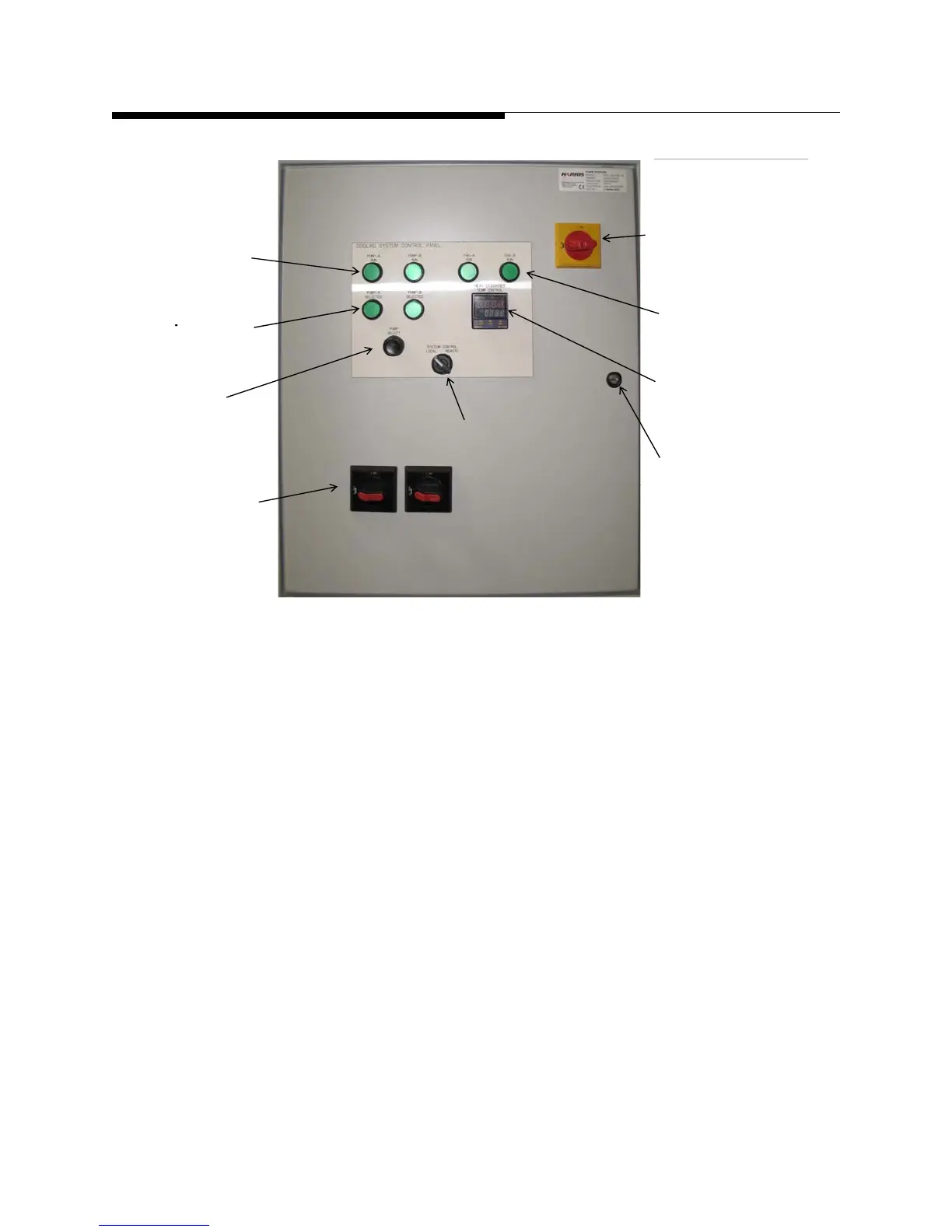
Figure 1-9 Cooling System Control Panel
The cooling system control panel shown in Figure 1-9 has local controls on the front
which allow manual selection of:
a. ISOLATOR ON/OFF
b. HEAT EXCHANGER FANS - Manual, OFF, or Remote
c. PUMP SELECT - A or B pump is selected when pressed
d. TEMP CONTROLLER - Sets fan cycle temps. Factory settings are Fan 1 set
point will be set at 32 C with a 5 degree hysteresis window. This means Fan 1
turns ON at 34.5 C and shuts off at 29.5 C. Fan 2 set point will be set at 37.5 C
also with a 5 degree hysteresis window. This means Fan 2 turns ON at 40 C and
shuts off at 35 C.
e. SYSTEM CONTROL - LOCAL/REMOTE - Allows local control or remote con-
trol via transmitter.
f. HEAT EXCHANGER TEMP CONTROL - PID controller used to set fan ON and
OFF temperatures.
The control panel also has the following status indicators:
g. PUMP - A RUN (ON = Green)
AC Isolator ON/OFF
Pum
A or B
ump
or
Run LEDs
FAN A or B
Selected LEDs
Pump
Controller
Set Temp. Set Point
System Control
LOCAL/OFF/REMOTE
Screwdriver Lock
Pump Isolators
ON/OFF
 Loading...

