Appendix 9 Zero Adjustment
A17
Appendix
To perform zero adjustment appropriately
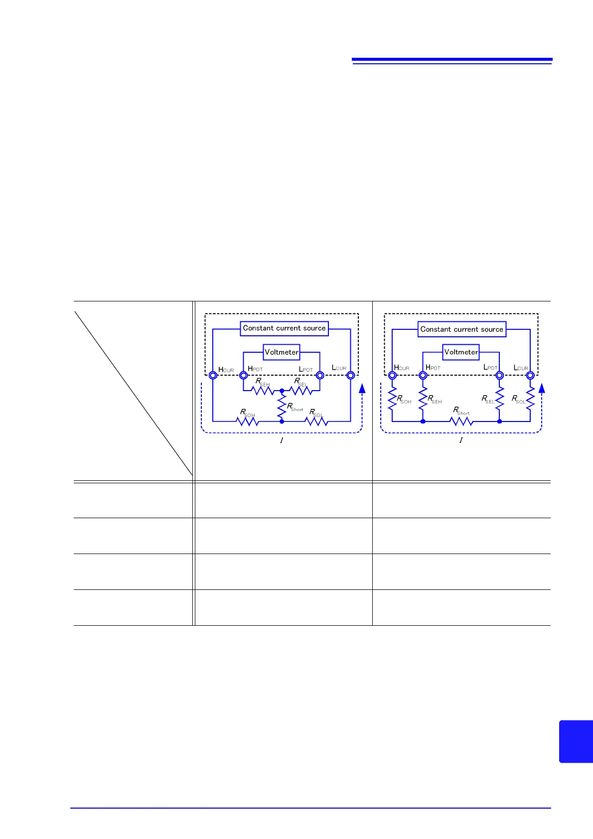
Table 1 shows the correct and wrong connections. The resistances in the figure
indicate lead resistances; there will be no problem if they are less than few
respectively
In (a), if you connect H
POT
and L
POT
as well as H
CUR
and L
CUR
respectively, and use
one path to make connection between POT and CUR, no potential difference occurs
between H
POT
and L
POT
, and 0 V is input. This enables zero adjustment to be carried
out correctly.
In (b), on the other hand, if you connect H
POT
and H
CUR
as well as L
POT
and L
CUR
respectively, and use one path to make connection between Hi and Lo, I × R
Short
voltage occurs between H
POT
and L
POT
. For this reason, the pseudo 0 connection
state cannot be achieved and zero adjustment cannot be carried out correctly.
Table 1: Connection methods
(a) Use one point each between
POT and CUR for connection
(b) Use one point each between
Hi and Lo for connection
Resistance between
H
POT
and L
POT
R
SEH
+ R
SEL
R
SEH
+ R
Short
+ R
SEL
Measurement current I's
flow path
R
SOH
R
SOL
R
SOH
R
Short
R
SOL
Voltage occurring
between
H
POT
and L
POT
0
I × R
Short
As connection method for
zero adjustment
Correct Wrong