Appendix 9 Zero Adjustment
A18
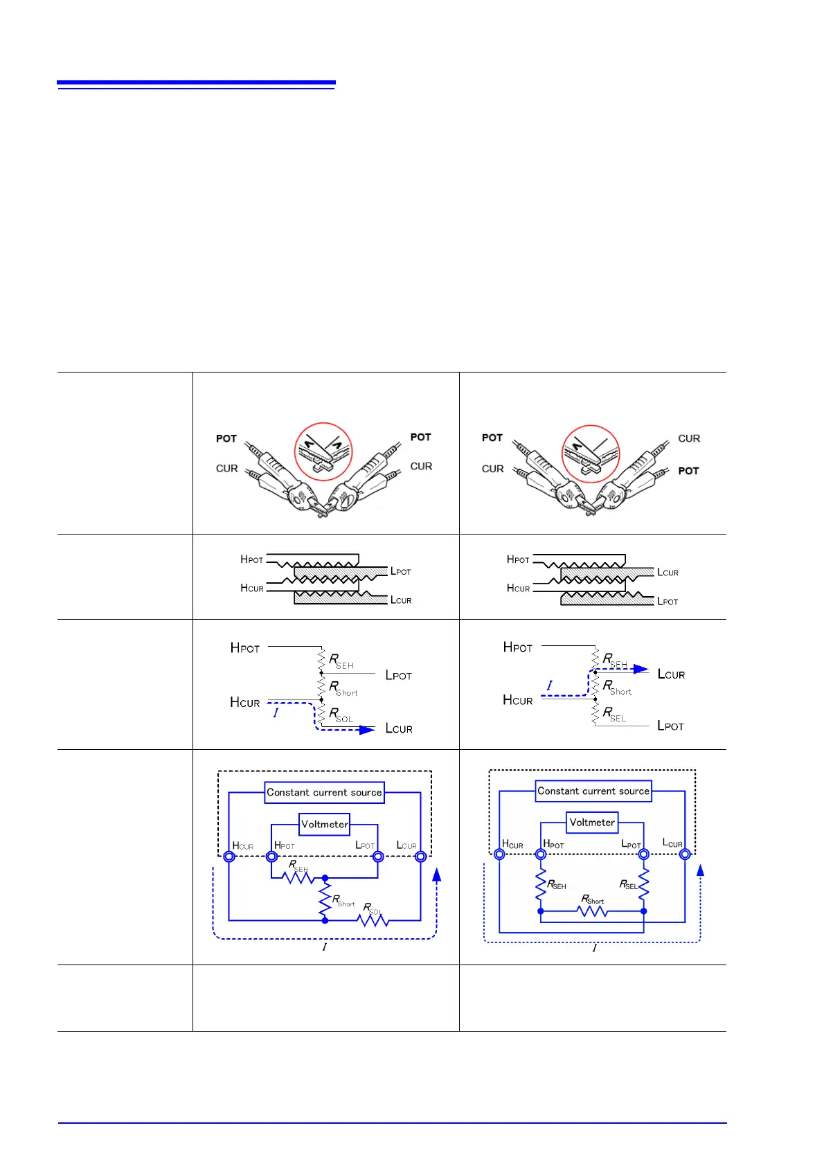
To perform zero adjustment using a probe
When you actually perform zero adjustment using a probe, you may unexpectedly
make the connection shown in Table 1 (b). Therefore, when performing zero
adjustment, you need to pay sufficient attention to the connection state of each
terminal.
Here, 9287-10 Clip Type Lead is used as an example for the connection explanation.
Table 2 shows the connection state of the tip of the lead and equivalent circuit in the
respective correct and wrong connections. Table 1 (a) indicates the correct
connection method, resulting in 0 V between H
POT
and L
POT
. However, Table 1 (b) is
the wrong connection method, so that 0 V is not obtained between H
POT
and L
POT
.
Table 2: Clip type lead connection methods used during zero adjustment
Connection method
Correct
Wrong
Tip of lead
Equivalent circuit
Deformed equivalent
circuit
As connection
method for zero
adjustment
Correct Wrong