2.2 Connecting Measurement Cables and Test Fixtures
23
2
Connect your measurement cables, optional Hioki probes or test fixture to the measurement jacks.
Refer to "Options" (p.4) for details. See the instructions provided with the fixture for operating
details.
2.2 Connecting Measurement Cables and
Test Fixtures
• Do not apply a voltage to the measurement terminals. Doing so may damage the unit.
• When disconnecting the BNC connector, be sure to release the lock before pulling off the
connector. Forcibly pulling the connector without releasing the lock, or pulling on the cable,
can damage the connector.
• We recommend using optional Hioki fix-
tures.
• Use the GUARD jack only for Faraday
shield, and avoid more than 10 mA cur-
rent flow. This jack is not for guarding
network resistance measurements.
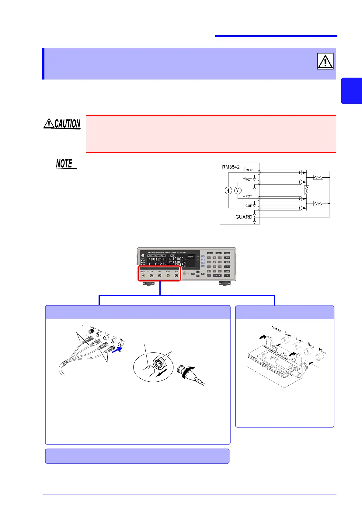
Example of defeated guard measurement
Connecting measurement cables
Connecting a fixture
Connect directly to the measurement
jacks with the label side up, and affix
with the levers on the left and right.
Connect the red plugs to the
H
CUR
and H
POT
jacks, and the
black plugs to the L
CUR
and
L
POT
jacks.
Black plugs
Red plugs
BNC Jack Guide Pins
(on the instrument)
Lock
BNC plug slots
2
1
Align the slots in the BNC plug with the
guide pins on the jack on the instrument,
then push and twist the plug clockwise
until it locks.
Disconnecting BNC connectors
Push the BNC plug, twist it counterclock-
wise, and pull it out.
Making your own probes and extenders (p. 24)
Connection Methods