4.9 Comparing the Measurement Settings of Two Instruments (Settings Monitor Function)
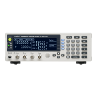
54
Tolerance Range Setting Conditions
5
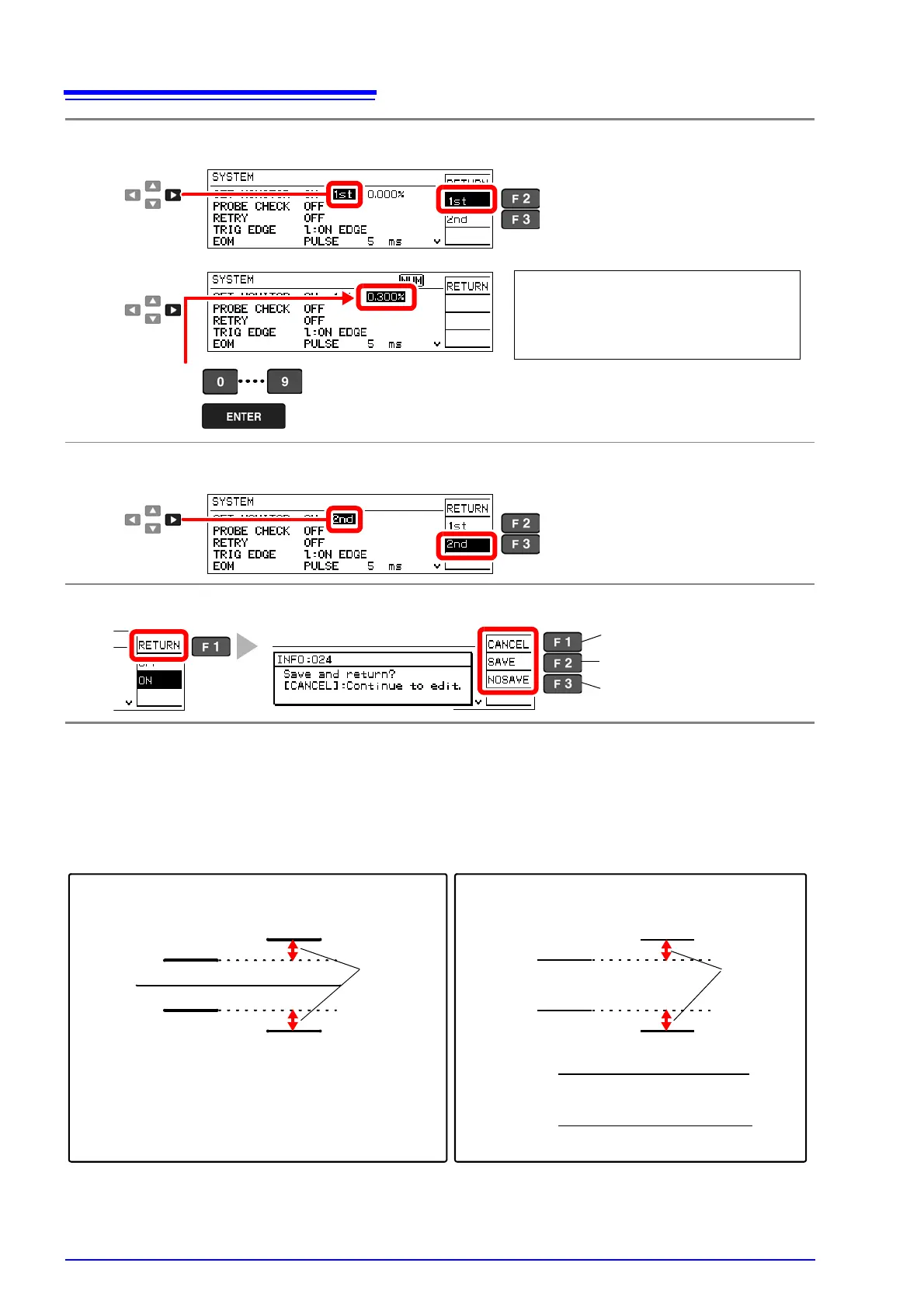
Select the instrument to serve as the 1st stage, and set its tolerance range.
6
Set the instrument to serve as the 2nd stage (another RM3542).
7
Return to the Measurement screen.
Selection
1
2
Selects this instrument as the 1st stage
Selects this instrument as the 2nd stage
3
Enter the difference in tolerance (%) to be allowed at the 2nd stage from the tol-
erance range set for the 1st stage.
Setting range: 0.000 to 9.999%
4
Example: If the 1st stage is set to measure
12
±0.800%, and the 2nd is to measure
12
±1.000%, enter the difference in toler-
ance of 0.300%.
Selection
1
2
Selects this instrument as the 1st stage
Selects this instrument as the 2nd stage
The confirmation screen appears.
Return to the setting screen.
Save setting and return to
previous screen.
Discard setting and return to
previous screen.
1st stage
2nd stage
UPP [%]
REF% setting ABS setting
REF [
]
LOW [%]
Tolerance
range [%]
UPP []
LOW [
]
2nd upper limit - 1st upper limit
1st upper limit
Tolerance range [%] > 2nd upper limit [%] - 1st upper limit [%]
Tolerance
range[%]
1st lower limit - 2nd lower limit
1st lower limit
(upper limit)
(
lower limit)
Permissible tolerance is calculated using floating-point values, so the setting must be at least 0.001% larger
than the difference between 2
nd
and 1
st
stage ranges. Set the upper and lower comparator thresholds ac-
cording to the following conditions:
1
st
stage upper threshold < 2
nd
stage upper threshold
1
st
stage lower threshold > 2
nd
stage lower threshold
(upper limit)
(
lower limit)
1st stage
2nd stage
Tolerance
range [%]
>
Tolerance
range[%]
>
x 100
x 100