Home
Hologic
Medical Equipment
Affirm
Page 97 (System Specifications)
Hologic Affirm - System Specifications; Affirm System Measurements
116 pages
Manual
Save Page as PDF
To Next Page
To Next Page
To Previous Page
To Previous Page
Loading...
Affirm Breast Biops
y Guidance
Sy
stem User Guid
e
Appendix
A
:
System
Specificati
ons
MAN
-
0641
1
-
002 R
evision
003
Page 85
Appendix A
S
ystem Sp
ecif
icatio
ns
A.
1
A
f
firm S
y
stem M
easurements
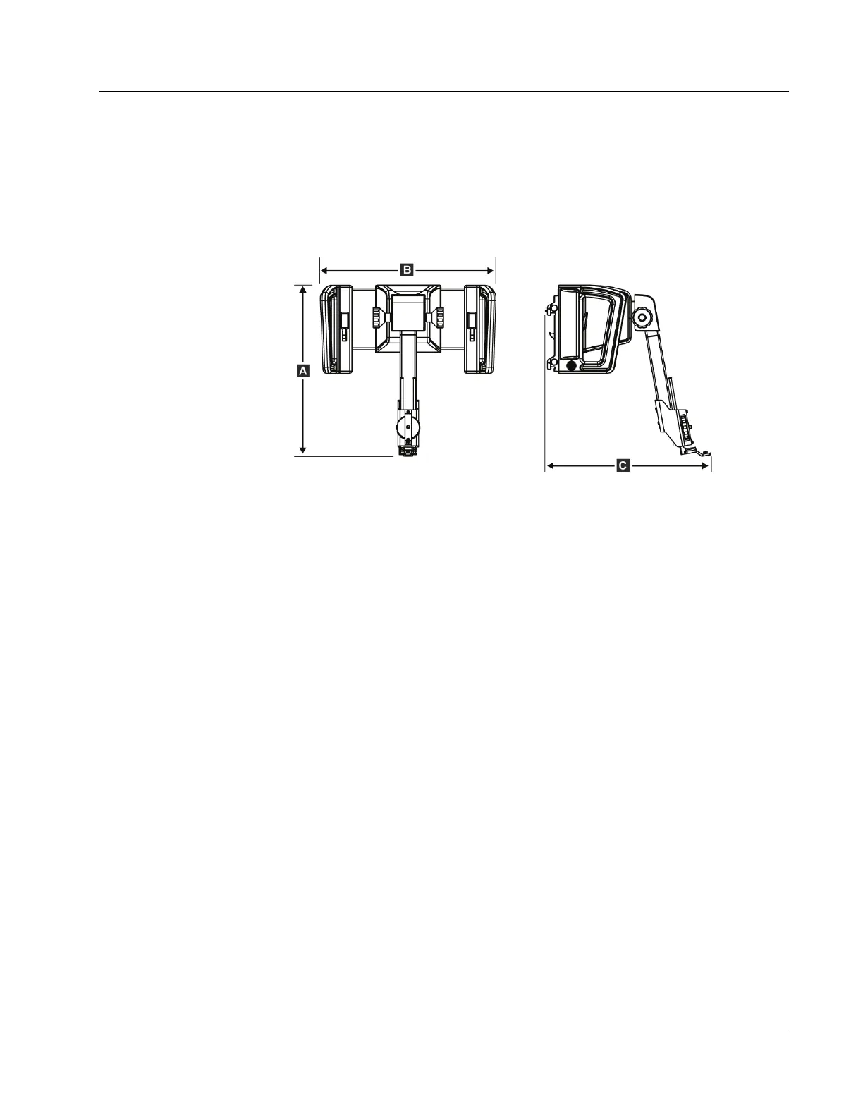
Figur
e 74:
Affirm Biopsy Guid
ance Mod
ule
A. Height
37.1 cm
(14.6
inches
)
B. Width
37.8 cm
(14.9
inches
)
C. Depth
35.6 cm
(14 in
ches)
Weight
6.8 k
g (15 pou
nds)
A
ppendix
A
96
98
Table of Contents
Main Page
Table of Contents
5
List of Figures
9
List of Tables
11
1: Introduction
13
Intended Use
13
User Profiles
13
Mammography Technologist
13
Radiologists, Surgeons
13
Medical Physicist
14
Training Requirements
14
Quality Control Requirements
14
Where to Find Technical Description Information
14
Warranty Statement
15
Technical Support
15
Product Complaints
15
Hologic Cybersecurity Statement
15
Symbols
16
Descriptions of Warnings, Cautions, and Notes
17
2: General Information
19
System Overview
19
Figure 1: Affirm Biopsy System on the Selenia Dimensions Mammography System
19
How to Handle the Biopsy Guidance Module
20
Figure 2: How to Lift the Biopsy Guidance Module
20
Figure 3: How to Store the Biopsy Guidance Module
20
Safety Information
21
Warnings and Precautions
21
Compliance
22
Compliance Requirements
22
Label Locations
23
Figure 4: Biopsy Guidance Module Label Location
23
Figure 5: Lateral Arm Serial Number Label Location
23
3: Installation, Verification, and Removal
25
Biopsy Guidance Module Components
25
Figure 6: Biopsy Guidance Module
25
Table 1: Components of the Biopsy Guidance Module
26
Biopsy Control Module Components
27
Figure 7: Biopsy Control Module
27
Table 2: Components of the Biopsy Control Module
27
Installation of the Main Components
28
Attach the Biopsy Guidance Module
28
Figure 8: Installation of the Biopsy Guidance Module
28
Attach the Biopsy Control Module
29
Figure 9: Attachment of the Biopsy Control Module
29
Installation and Removal of Accessories
30
Biopsy Compression Paddles
30
Needle Guide
30
Figure 10: Installation of the Needle Guide Holder on the Standard Device Mount
31
Figure 11: Installation of the Needle Guide on the Standard Needle Guide Holder
31
Biopsy Device Adapter
32
Biopsy Device
32
Figure 12: Attaching a Biopsy Device Adapter to the Device Mount (Standard)
32
Lateral Arm and Lateral Arm Accessories
33
Figure 13: Lateral Arm Components
33
Table 3: Components of the Lateral Arm
34
Figure 14: Left Needle Approach of Lateral Arm (Blue)
35
Figure 15: Right Needle Approach of Lateral Arm (Yellow)
35
Figure 16: Installing the Lateral Arm Stand over the Image Receptor
36
Figure 17: Removing the Needle Guide Holder from the Standard Device Mount
37
Figure 18: Installing the Lateral Arm on the Device Mount
38
Figure 19: Selection Screen for the Lateral Arm Mounting Side
39
Figure 20: Attaching the Blue Needle Guide Holder to the Needle Guide Rods (Left Needle Approach)
40
Figure 21: Attaching the Yellow Needle Guide Holder to the Needle Guide Rods (Right Needle Approach)
40
Figure 22: Installing a Disposable Needle Guide on a Needle Guide Holder (Lateral Arm)
41
Figure 23: Carriage Lever Locked and Unlocked Positions
42
Figure 24: Locked and Unlocked Positions of Device Mount Lever
42
Figure 25: Installing Device Mount Onto Lateral Arm Carriage
43
Figure 26: Attaching the Biopsy Device Adapter to the Device Mount (Lateral Arm)
44
Figure 27: Lock Levers in Fully Locked Position
45
Figure 28: Scales and Positioning for the X-Stop and Carriage
46
Figure 29: Installing the X-Stop on the Lateral Arm
47
System Verifications
48
Confirm the Host Connection
48
Figure 30: Home Screen on the Biopsy Control Module
48
Removal of the Main Components
49
Biopsy Control Module
49
Biopsy Guidance Module
49
Tabletop Stand for the Affirm System
50
Figure 31: Affirm System Tabletop Stand
50
Storage Case for the Lateral Arm
51
Figure 32: Lateral Arm and Storage Case
51
4: User Interface - Biopsy Control Module
53
Biopsy Control Module Screens
53
Home Screen
53
Figure 33: Home Screen
53
Target Guidance Screen
54
Figure 34: Target Guidance Screen
54
Figure 35: Target Guidance Screen for Lateral Arm
55
Figure 36: Green Differential Cells
56
Figure 37: Yellow and Red Cells
56
Figure 38: Alert Sounds Are Audible
57
Figure 39: Alert Sounds Are Muted
57
Table 4: How to Use the Sound Button
57
Jog Mode Screen
58
Figure 40: Jog Mode Screen
58
Figure 41: Jog Mode Screen for Lateral Arm
59
Select Target Screen
60
Figure 42: Select Target Screen
60
5: Biopsy
63
Biopsy Views
63
Add a Biopsy View
64
Edit a Biopsy View
66
C-Arm Stereo Modes
67
C-Arm Rotation in the C-Arm Stereo Modes
67
Table 5: the C-Arm Stereo Mode Button
68
How to Select the C-Arm Stereo Mode for Image Acquisition
69
Table 6: How to Select the C-Arm Stereo Mode
69
Biopsy Tab
70
Biopsy Options
71
Stereotactic 2D Lesion Targeting
74
Verify the Position of the Biopsy Device
75
Lesion Targeting with Tomosynthesis Guidance
76
Verify the Position of the Biopsy Device
77
Project Targets on Post-Fire Scout Image
77
Lesion Targeting Using Multi-Pass
78
Post Biopsy
82
Printing Stereo Pair Images
82
6: Quality Control
83
Required Quality Control Procedures
83
QAS Test
83
Table 7: Required Procedures
83
QAS Test for Standard Needle Approach
84
QAS Test for Lateral Needle Approach
87
Geometry Calibration
90
Geometry Calibration Procedure
90
7: Care and Cleaning
91
General Information
91
Preventive Maintenance Schedule
91
Table 8: Radiologic Technologist Preventive Maintenance Schedule
91
Table 9: Radiologic Technologist Preventive Maintenance Schedule
92
Service Preventive Maintenance Schedule
93
Table 10: Service Engineer Preventive Maintenance Schedule
93
For General Cleaning
94
How to Clean the Biopsy Control Module Screen
94
To Prevent Possible Injury or Equipment Damage
95
Appendix A: System Specifications
97
Affirm System Measurements
97
Lateral Arm Measurements
98
Biopsy Guidance Module
99
Lateral Arm
99
Biopsy Control Module
99
Appendix B: System Messages and Alerts
101
Audible Alerts
101
Error Messages
101
Table 11: Affirm System Audible Alerts
101
Table 12: Affirm System Error Messages
101
Acquisition Workstation Messages
103
Table 13: Acquisition Workstation Messages
103
Appendix C: CNR Correction for Biopsy
105
CNR Correction for Stereotactic 2D Biopsy
105
AEC Table 0 (Standard Stereotactic 2D Biopsy Dose)
105
CNR Correction for Biopsy under Tomosynthesis Option
105
AEC Table 0 (Tomosynthesis Option: Standard Tomo Dose)
105
Appendix D: Forms
107
QAS Test Checklist
107
QAS Test Checklist for the Lateral Arm
108
Appendix E: Ancillary Parts for Biopsy
109
Hologic Factory-Verified Biopsy Devices
109
Table 14: Hologic Factory-Verified Biopsy Devices
109
Wire Localization Needle Guides
110
Table 15: Wire Localization (Loc) Needle Guides
110
Glossary of Terms
111
Index
113
Other manuals for Hologic Affirm
Service Manual
116 pages
Related product manuals
Hologic DISCOVERY A
274 pages
Hologic ATEC SAPPHIRE
36 pages
Hologic SUROS ATEC Pearl
48 pages
Hologic NovaSure Advanced
31 pages
Fluoroscan InSight 2 Mini C-arm
89 pages
Fluoroscan InSight FD Mini C-arm
88 pages
Hologic Trident HD
96 pages
Hologic 3Dimensions
100 pages
Hologic SecurView DX
54 pages
Hologic selenia dimensions
104 pages
Hologic DISCOVERY QDR Series
274 pages
CYNOSURE ELLMAN SURGITRON 4.0 Dual RF/90 IEC
32 pages