78 MPA2C3 User Manual
Creating Interlocks
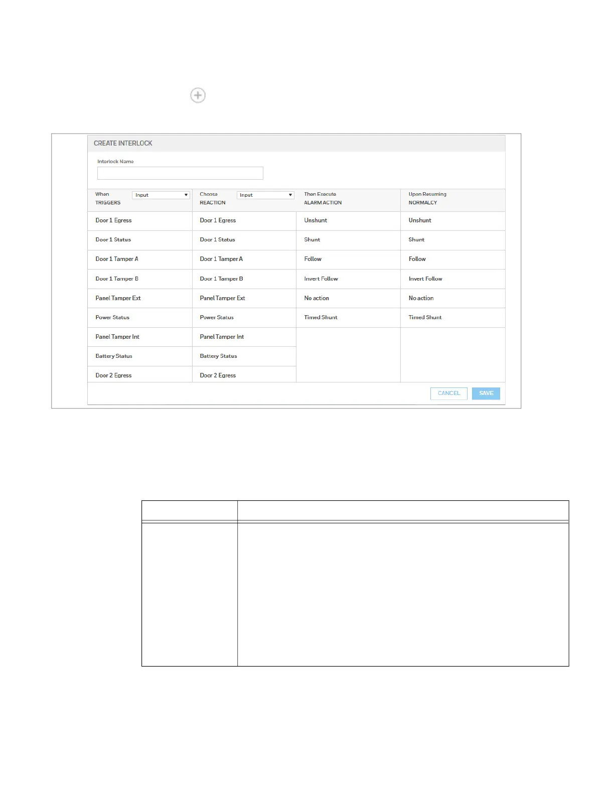
1. Click to open the Create Interlock window.
Figure 2-36 Create Interlocks Interface
2. Enter a name for the new Interlock.
3. Select configurations for the Triggers (Input, Output, or Group), Reaction
(Input, Output, or Group), Alarm Action, and Normalcy (the state to which the
trigger returns).
Table 2-15
Configuration Description
Triggers
Specifies the input, output, or output group for which a change of state will cause a
reaction from another input, output, or group.
If
Trigger = Inputs, then triggers 1-88* will have an interlock link (Int Lnk) number
from 1-96.
If
Trigger = Outputs, then outputs 1-80* will have an interlock link (Int Lnk)
number from 97-184.
If
Trigger = Groups, then groups 1-64* will have an interlock link (Int Lnk) number
from 185-250.
Use the drop-down list to specify the number of the input or output.
Additional Input/Output/Group points are achieved with the addition of NX4IN and
NX4OUT secondary devices.