HP 8114A Service Guide
Removing the Output Board
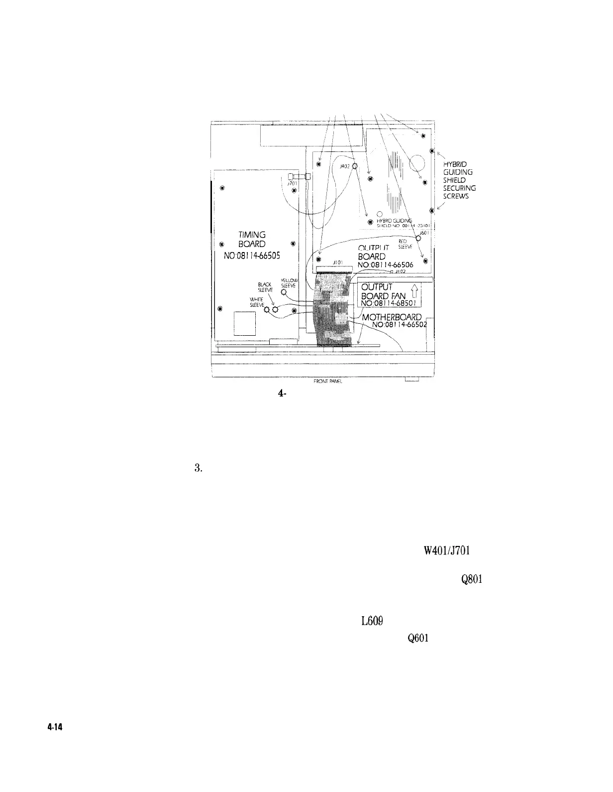
OUTPUT BOARD
SECURING SCREWS
NO08114-66505
Figure
4-
11. Location of the Output Board
I. Follow the instructions for Removing the Instrument Cover.
2. Remove the 2 screws securing the hybrid module guiding shield.
See Figure 4-l 1.
3.
Release the hybrid module guiding shield from the 2 clips.
4. Disconnect the ribbon cable, 5101, which is close to the front
panel.
5. Disconnect the fan cable, 5102.
6. Disconnect the output cable, 5601.
7. Disconnect the two cables close to the rear panel,
W401/5701
on
the timing board, and 5402 on the output board.
8. Remove the 2 screws securing the holder of the transistors
Q801
to Q804 to the chassis, the holder is placed between the fan and
the hybrid modules.
9. Remove the screw securing the coil
L609
to the chassis.
10. Remove the 2 screws securing the power FET
Q601
to the chassis,
The FET is located between the hybrids. See Figure 4-12.
4.14
Disassembly and Reassembly