HP 8114A Service Guide
On the Power Supply Board:
1. Connect the cable from the isolating mains transformer to the
mains power connector
2. Connect the fan to 5401 from pin 32b to pin
32~.
This is essential
as the Power Supply will not run with the fan disconnected
3. Connect the
30R
load resistor to
t,he
-5.2 V supply, from
5401
pin
26a (-5.2 V) to pin 24a (AGND)
4. Connect the
1000
load resistor to the + 10
VFL
supply, from
5401
pin 8a
(t
10 VFL) to pin 2a (FLGND)
5. Apply power to the isolating transformer and observe the fans.
If the fans are not running:
1. Disconnect mains power and check that the fans are physically OK,
that is free from damage or obstruction
2. Using an Ohmmeter check for
<
1
fl
continuity: the main fuse,
FH401, inductor T400, switch
S401,
filter
MP123
and the mains
cable, including any fuse fitted in the power plug.
SCR Q401 suppresses low impedance voltage peaks on the supply
line. If this SCR fails, it may not be immediately noticeable, but
test-bench fuses may fail if high line voltage peaks occur during
high current operation of the HP 8114A.
Warning
Voltages are present which can be hazardous to life.
Power Supplies
Fixed Supplies
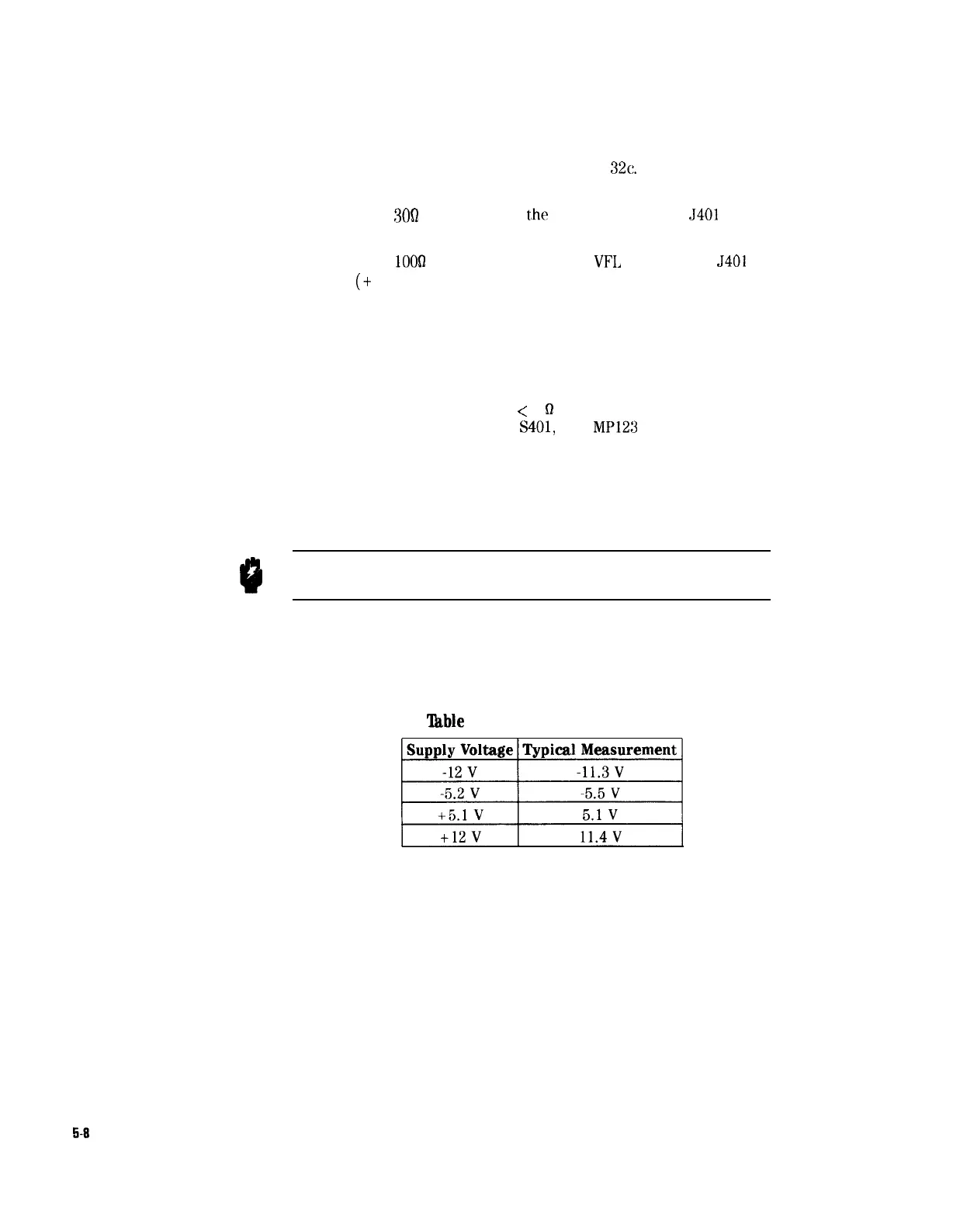
1. Check the fixed supplies agaist AGND at testpoint TP2:
‘lkble
5-2. Fixed Power Supplies
Supply Voltage Typical Measurement
ppJj
5-8
Troubleshooting