HP 8114A Service Guide
Removing the Front Panel
1.
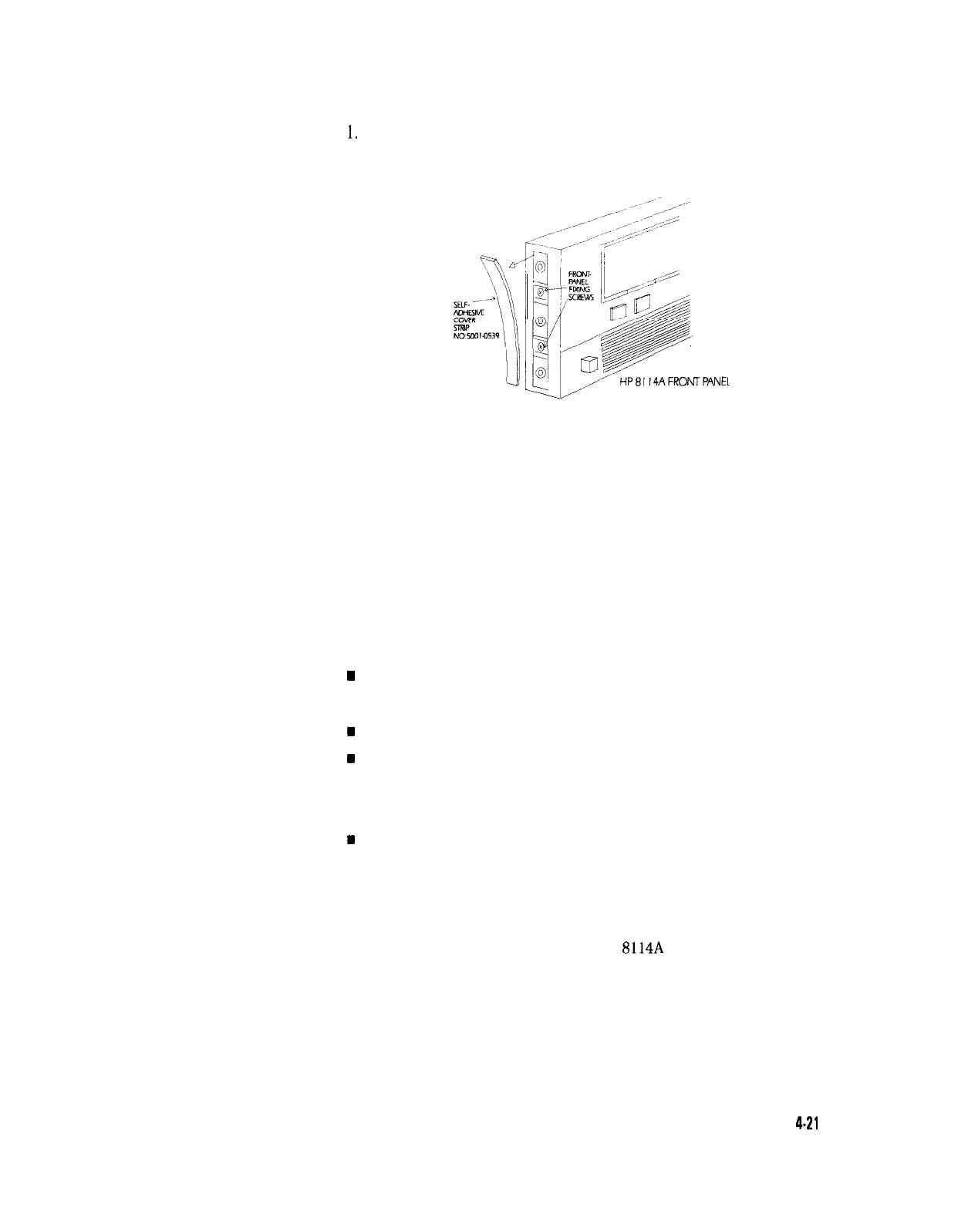
Remove the 2 self-adhesive side trims. These cover the Front Panel
fixing screws. See Figure 4-16 for the position of the trims
Figure 4-16. Front Panel Fixing Screws
2. Remove the 4 screws (2 on each side of the Front Panel) securing
the Front Panel to the chassis
3. Pull the Front Panel forward from the chassis and disconnect the
long ribbon cable connected to the Motherboard connector on the
front of the chassis
4. Remove the Front Panel
The replaceable subassemblies of the Front Panel are:
n Ribbon-cable connecting the Front Panel to the Motherboard
n
Ribbon-cable connecting the RPG module to the Display module
w
Display module
n
RPG module
m
RPG knob
m
RPG Head unit
n Key pad retaining panels
n
Key pad flexible connector
m
Large Key pad
n
Small Key pad
n
Front Panel Legend Foil
n
Front Panel frame
Figure 4-17 shows a rear view of the HP
8114A
Front Panel. For
clarity, the 2 ribbon-cables are not shown.
Disassembly and Reassembly
4.21