Test 5.3: Delay Jitter
Test Specifications
Equipment Needed
Procedure
RMS-Jitter
0.03%
+
25 ps (0.05% + 25 ps for 50 ns
<
delay
<
100 ns)
Digitizing Oscilloscope with Accessories
All cables: 50
0,
coaxial, BNC, 122cm (4ft)
High Power Attenuator
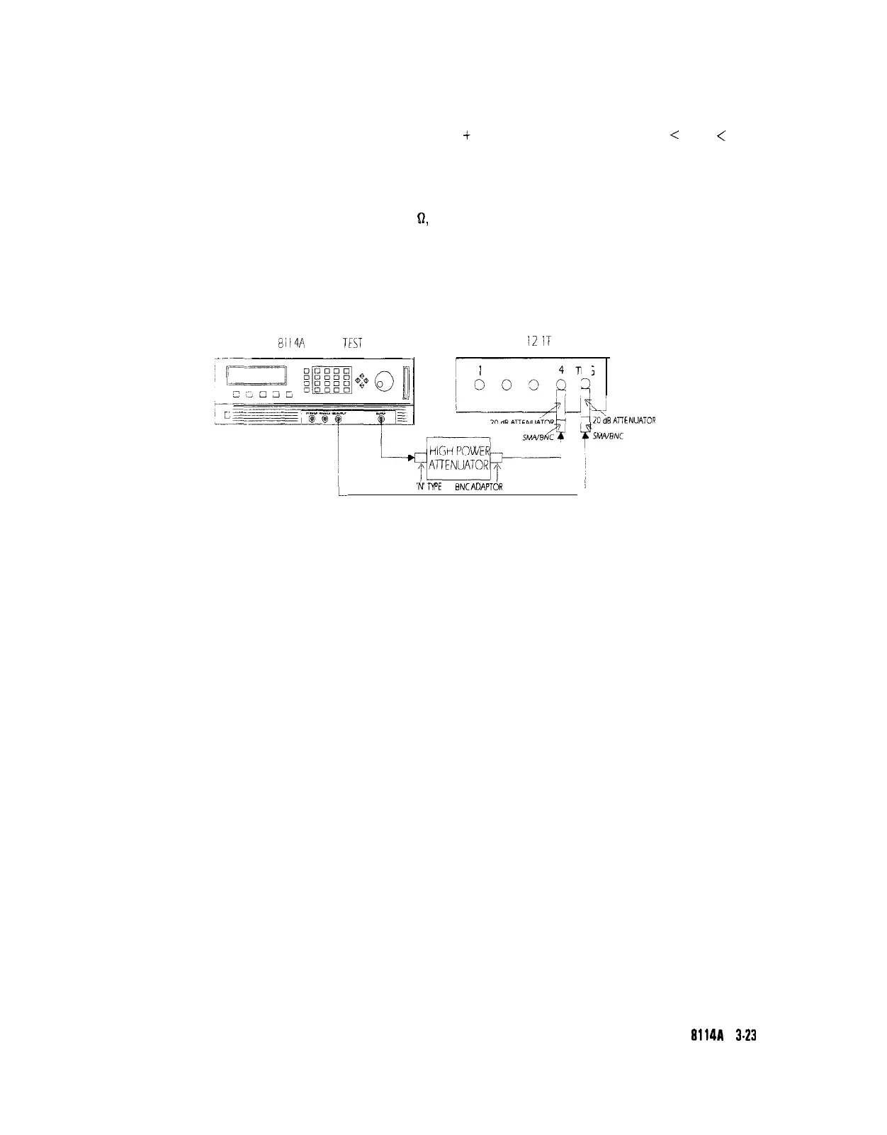
1. Connect HP 8114A to the Scope as shown:
HP
81
l4A
UNDER
TEST
HP 54
12
ii
FRONT-END
/
I
2 3
4T
Iooqi
RIC
1
ADAPTOR ,
W
‘WE
TO
BNCADAPTOR
Equipment Set-up for Delay Jitter Test
i
4
2O\dBAl7ENUATOR
\
ShwBNC
ADAPTOR
2. For calculating the RMS-jitter, the rise time of the reference signal
within a 1% amplitude window is required. If this value is not,
already measured in the Period Jitter test, then perform the first, 6
steps of the Period Jitter test.
Testing the HP
g114A
3.23