HP
8114A Service Guide
OUTPUT
BOARD
NO08i
14
66506
POWER
FFT
-3
POWER LOAD
9
RESISTOR
8
----j
JIO
I
-_I
1
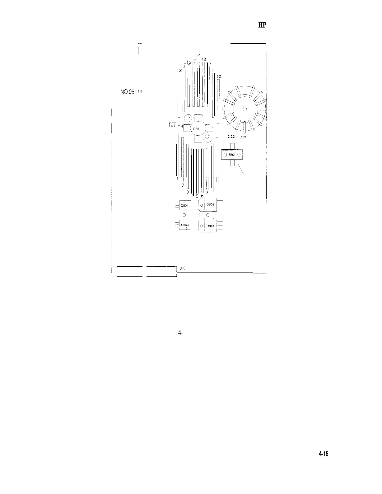
Figure 4-12. Location of the Power Load Resistor and Power FET
11. Remove the 2 screws securing the power load resistor R601 to the
chassis. The power load resistor is located close to one hybrid
stage. See Figure 4-12.
12. Remove the 7 screws securing the output board to the chassis.
See Figure
4-
11.
13. Lift the output board up at the fan at the front panel side, and
pull it out towards the front panel side.
Disassembly and Reassembly
4-15