ELP
8114A Service Guide
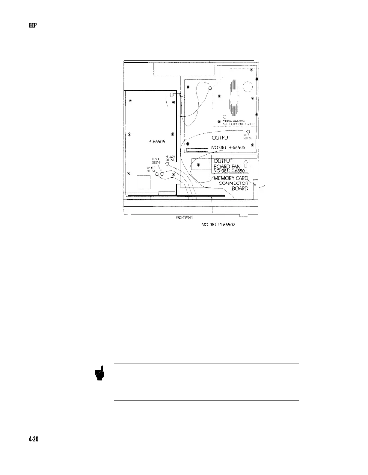
Removing the Memory-Card Connector Board
TIMING
@a
BOARD
@
NO081
14-66505
1.
?:
BOARD
NO~08114-66506
'
FROM
PANEL
L
MOTHERBOARD
NO,08114-66502
,.
SECURING
SCREW
Figure 4-15. Location of the Memory-Card Connector Board
1. Follow the instructions for Removing the Instrument Cover.
2. Disconnect the 2 ribbon cables connecting the memory-card
connector board to the motherboard.
3. Follow the instructions for Removing the output board fan.
4. Remove the screw securing the memory-card connector board to
the chassis. The screw is located at the outside of the chassis. See
Figure 4-15.
5. Remove the two screws securing the memory-card connector board
to the metal holder.
Refitting the Memory-Card Connector Board
Refitting the memory-card connector board is the reverse procedure
of removal. Pleae note the following:
Note
Insert the two guiding spacers of the memory-card connector board
into the two holes in the chassis.
Secure the memory-card connector
board
with the screw, p/n
0515-0886, from the outside of the chassis.
4-20
Disassembly and Reassembly