FIP
8114A Service Guide
13. A negative pulse with an amplitude of 15.99 V should be
monitored.
14. Set the output ampliude to 50.0 V.
15. Mount hybrids number 10 through 18 in their sockets.
16.
Finally a negative pulse with an amplitude of 50.0 V should be
monitored.
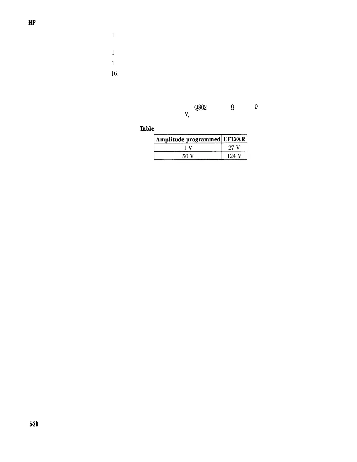
Variable Floating Supply (UFLVAR)
Check UFLVAR at the emitter of
&SO2
in the 50
0
into 50
s2
mode,
with variable baseline of 0.0
V,
and in negative pulse mode.
‘able
5-12. Variable Floating Supply UFLVAR
Ei
Relays
1. Check for switching noise when toggling the relays.
2. If all relays don’t switch the relay driver 17601 may be defective.
5.20 Troubleshooting