EIP
8114A Service Guide
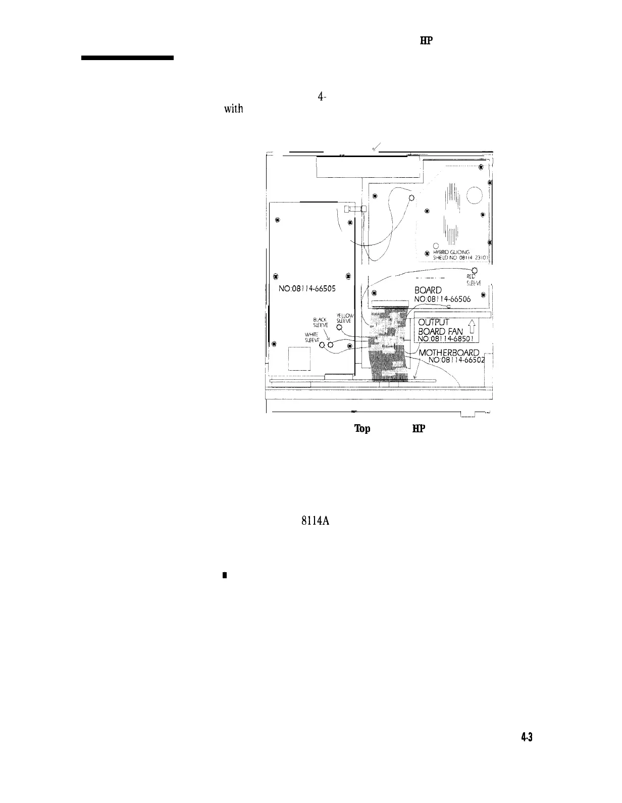
Inside the HP 8114A
‘lake a look at Figure
4-
1. It shows the top view of an instrument
wit,h
the case removed.
%/
POWER SUPPLY SLIDE
------
.-
I
@
TIMING
0
BOARD
@
NO:08114-66505
/ ’
_..,._
----------g
~
/
/,,A-
OUTPUT
i$w
/ 1
I
-.
1-A
.i
FROM PANEL
Figure 4-1.
Top
View of
HP
8114A
There is direct access to the Timing board, and the output board.
Access to the microprocessor board is possible when the power supply
slide is removed. On the power supply slide, the power supply unit,
power supply fan, and the optional variable baseline is mounted. The
power supply slide is is removable or refittable at the rear panel side.
The Standard HP
8114A
contains:
n
Power Supply Unit
n
MPU board
I
Timing board
n
Output board
In addition, the instrument may have been optionally fitted with, or
retrofitted with the following board:
n Variable Baseline
Also, the BNC Input/Output connectors can be on the front or the rear
panel, according to original customer requirements.
Disassembly and Reassembly
4-3