121
Tunable Laser Sources
How to Modulate a Signal
CAUTION There are two BNC connectors on the front panel of the HP 81680A,
HP 81682A, and HP 81640A - a BNC input connector and a BNC output
connector.
An absolute maximum of ± 6 V can be applied as an external voltage to any
BNC connector.
To enable wavlength locking:
1 Move to the Tunable Laser channel and press [Details].
2 Move to <MOD SRC> and press ENTER.
3 Move to <WAVEL.LOCKING>, by using the cursor key, and press
ENTER. The text λLock appears in the Tunable Laser channel.
External Digital Modulation using Input Trigger Connector
External digital modulation uses a TTL-level signal. Apply this
signal to the Input Trigger connector on the rear panel of the
HP 8163A Lightwave Multimeter or the HP 8164A Lightwave
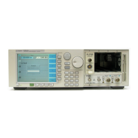
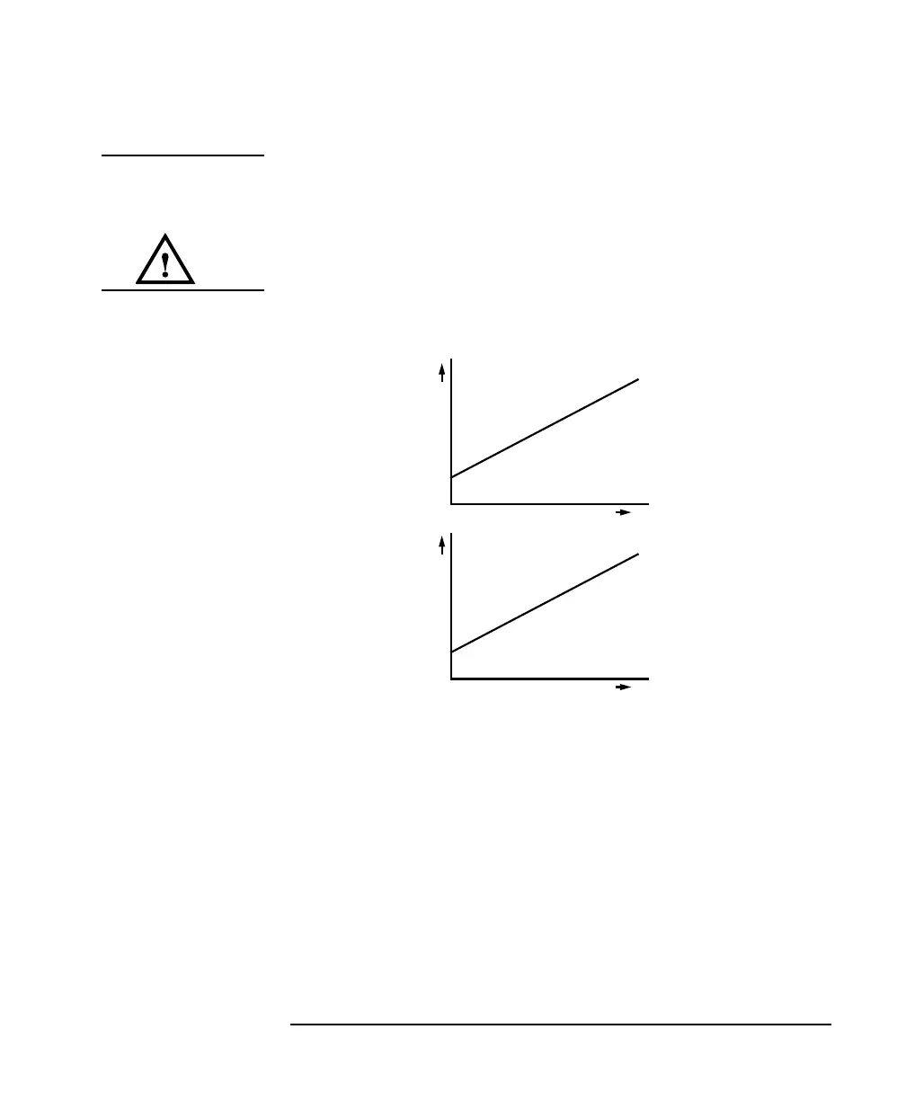
Figure 5-16 Wavelength Locking
t
V
t
λ