3 Identifying System Components and Numbering
NOTE: The illustrations in this chapter are examples only and might not accurately represent
your storage-system configuration.
Due to the large number of prospective configurations, component placement and internal cabling
is standardized to simplify installation and maintenance. System components are placed in the
rack according to the principles outlined in this chapter, and are numbered according to their
order and location in the cabinet.
Bezel
Bezel LEDs
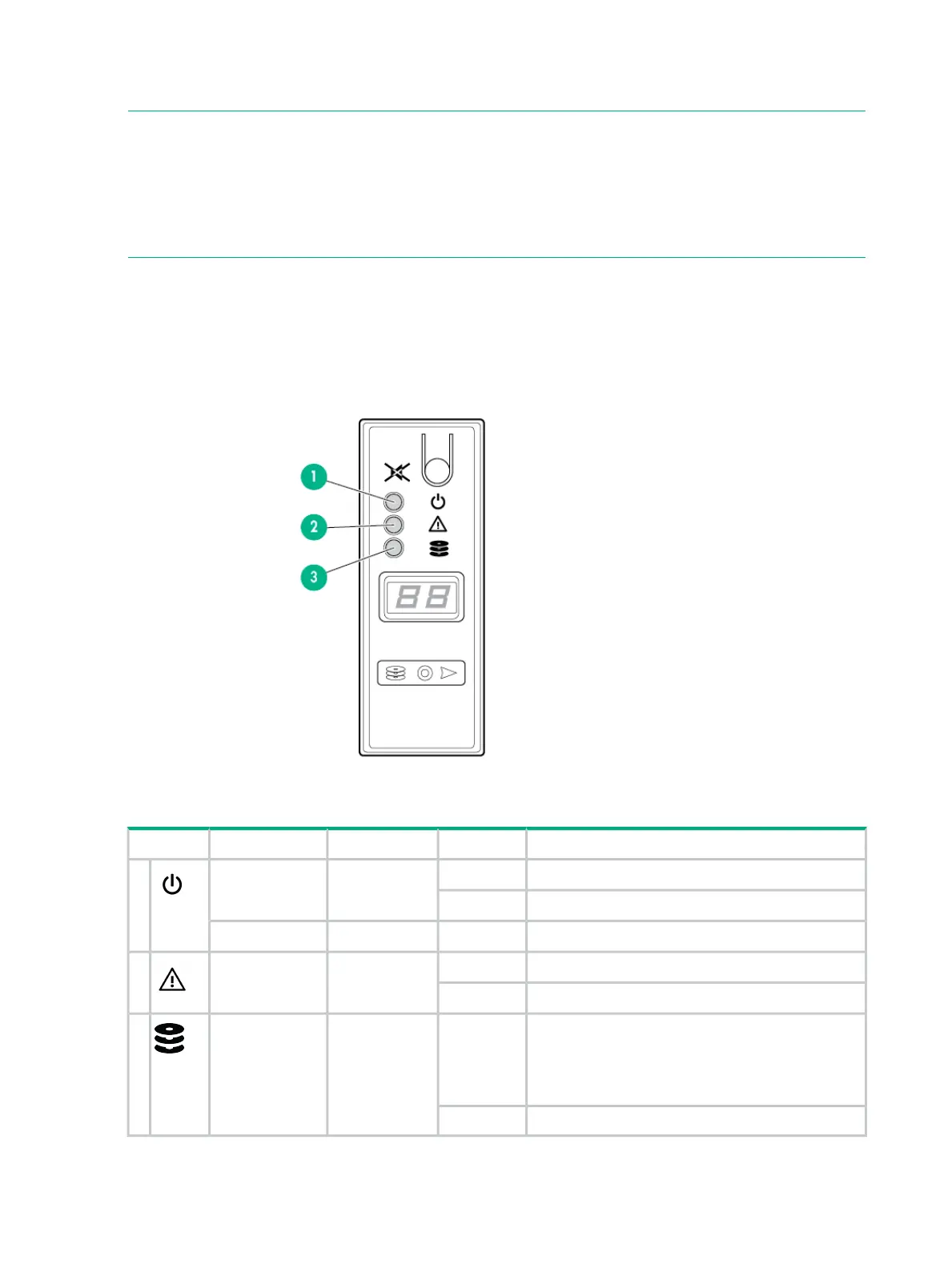
Figure 1 Bezel LEDs location
Table 2 Bezel LEDs description
IndicatesStateAppearanceFunctionLED Icon
PowerOnGreenSystem Power1
No powerOff
Enclosure powered by the batteryOnAmberSystem Standby
FaultOnAmberModule Fault2
No faultOff
Fault—An issue exists with one or more drives within
the enclosure. Inspect the LEDs on each drive to
determine the affected drive(s).
OnAmberDrive Status3
This LED applies only to drives.
No faultOff
14 Identifying System Components and Numbering
 Loading...