Figures
11
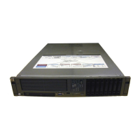
Figure 1-1. HP Integrity rx4640 Server with Front Bezel. . . . . . . . . . . . . . . . . . . . . . . . . . . . . . . . . 20
Figure 1-2. HP Integrity rx4640 Server (front view with bezel removed) . . . . . . . . . . . . . . . . . . . . 21
Figure 1-3. HP Integrity rx4640 Server (rear view). . . . . . . . . . . . . . . . . . . . . . . . . . . . . . . . . . . . . . 21
Figure 2-1. Front View with Bezel . . . . . . . . . . . . . . . . . . . . . . . . . . . . . . . . . . . . . . . . . . . . . . . . . . . 26
Figure 2-2. Accessing the Control Panel . . . . . . . . . . . . . . . . . . . . . . . . . . . . . . . . . . . . . . . . . . . . . . . 26
Figure 2-3. Control Panel LEDs . . . . . . . . . . . . . . . . . . . . . . . . . . . . . . . . . . . . . . . . . . . . . . . . . . . . . 27
Figure 2-4. Hard Disk Drive LED Indicators . . . . . . . . . . . . . . . . . . . . . . . . . . . . . . . . . . . . . . . . . . . 27
Figure 2-5. DVD–ROM Drive . . . . . . . . . . . . . . . . . . . . . . . . . . . . . . . . . . . . . . . . . . . . . . . . . . . . . . . 28
Figure 2-6. Rack Mount and Pedestal Rear View. . . . . . . . . . . . . . . . . . . . . . . . . . . . . . . . . . . . . . . . 28
Figure 2-7. Power Supply Status LEDs . . . . . . . . . . . . . . . . . . . . . . . . . . . . . . . . . . . . . . . . . . . . . . . 29
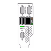
Figure 2-8. MP LAN LEDs . . . . . . . . . . . . . . . . . . . . . . . . . . . . . . . . . . . . . . . . . . . . . . . . . . . . . . . . . 29
Figure 2-9. Core I/O LAN Port LEDs . . . . . . . . . . . . . . . . . . . . . . . . . . . . . . . . . . . . . . . . . . . . . . . . . 30
Figure 2-10. QuickFind Diagnostic Panel . . . . . . . . . . . . . . . . . . . . . . . . . . . . . . . . . . . . . . . . . . . . . . 31
Figure 2-11. I/O Baseboard LEDs, Buttons, and Sensors . . . . . . . . . . . . . . . . . . . . . . . . . . . . . . . . . 32
Figure 4-1. Accessing 25MM Torx Screws . . . . . . . . . . . . . . . . . . . . . . . . . . . . . . . . . . . . . . . . . . . . . 39
Figure 4-2. Pedestal Mounted HP Integrity rx4640 Server. . . . . . . . . . . . . . . . . . . . . . . . . . . . . . . . 40
Figure 4-3. Removing and Replacing the Front Bezel . . . . . . . . . . . . . . . . . . . . . . . . . . . . . . . . . . . . 41
Figure 4-4. Removing and Replacing the Front Cover. . . . . . . . . . . . . . . . . . . . . . . . . . . . . . . . . . . . 42
Figure 4-5. Removing and Replacing the Top Cover . . . . . . . . . . . . . . . . . . . . . . . . . . . . . . . . . . . . . 43
Figure 4-6. Opening the Memory Extender Board Latches . . . . . . . . . . . . . . . . . . . . . . . . . . . . . . . 45
Figure 4-7. Removing and Replacing the Memory Extender Board. . . . . . . . . . . . . . . . . . . . . . . . . 45
Figure 4-8. Inserting DIMM into Extender Board Slot . . . . . . . . . . . . . . . . . . . . . . . . . . . . . . . . . . . 48
Figure 4-9. 16 DIMM Extender Board Slot IDs . . . . . . . . . . . . . . . . . . . . . . . . . . . . . . . . . . . . . . . . . 49
Figure 4-10. 32 DIMM Extender Board Slot IDs . . . . . . . . . . . . . . . . . . . . . . . . . . . . . . . . . . . . . . . . 50
Figure 4-11. Opening the Processor Extender Board Latches . . . . . . . . . . . . . . . . . . . . . . . . . . . . . 53
Figure 4-12. Removing and Replacing the Processor Extender Board. . . . . . . . . . . . . . . . . . . . . . . 53
Figure 4-13. Processor Slot Locations on the Processor Extender Board . . . . . . . . . . . . . . . . . . . . . 56
Figure 4-14. Removing the Processor Sequencer . . . . . . . . . . . . . . . . . . . . . . . . . . . . . . . . . . . . . . . 57
Figure 4-15. Unlocking the Processor from the Processor Extender Board. . . . . . . . . . . . . . . . . . . 58
Figure 4-16. CPU 1 Socket Unlocked . . . . . . . . . . . . . . . . . . . . . . . . . . . . . . . . . . . . . . . . . . . . . . . . . 59
Figure 4-17. Processor Cable Routed Correctly. . . . . . . . . . . . . . . . . . . . . . . . . . . . . . . . . . . . . . . . . 60
Figure 4-18. Locking the Processor to the Processor Extender Board . . . . . . . . . . . . . . . . . . . . . . . 61
Figure 4-19. Installing Sequencer on Extender Board . . . . . . . . . . . . . . . . . . . . . . . . . . . . . . . . . . . 62
Figure 4-20. Removing and Replacing the Chassis Fans 0 and 1. . . . . . . . . . . . . . . . . . . . . . . . . . . 64
Figure 4-21. Removing and Replacing the Chassis Fan 2 . . . . . . . . . . . . . . . . . . . . . . . . . . . . . . . . . 65
Figure 4-22. I/O Baseboard Locking Lever . . . . . . . . . . . . . . . . . . . . . . . . . . . . . . . . . . . . . . . . . . . . 67
Figure 4-23. Removing the I/O Baseboard . . . . . . . . . . . . . . . . . . . . . . . . . . . . . . . . . . . . . . . . . . . . . 68
Figure 4-24. I/O Baseboard Dip Switches . . . . . . . . . . . . . . . . . . . . . . . . . . . . . . . . . . . . . . . . . . . . . 69
Figure 4-25. Slot ID Numbering . . . . . . . . . . . . . . . . . . . . . . . . . . . . . . . . . . . . . . . . . . . . . . . . . . . . . 76
Figure 4-26. PCI-X OLX Divider Layout . . . . . . . . . . . . . . . . . . . . . . . . . . . . . . . . . . . . . . . . . . . . . . 78
Figure 4-27. Inserting PCI-X Card . . . . . . . . . . . . . . . . . . . . . . . . . . . . . . . . . . . . . . . . . . . . . . . . . . . 79
Figure 4-28. Opening and Closing the OLX Divider Latch. . . . . . . . . . . . . . . . . . . . . . . . . . . . . . . . 82
Figure 4-29. Removing and Replacing the OLX Divider. . . . . . . . . . . . . . . . . . . . . . . . . . . . . . . . . . 83

 Loading...


