Chapter 4
Removing and Replacing Components
Removing and Replacing a Processor
55
Removing and Replacing a Processor
Us the following procedures to remove and replace a processor on the processor extender board. Processors
are located on the top and bottom surfaces of the processor extender board.
WARNING Ensure that the server is powered down and all power sources have been
disconnected from the server prior to removing or replacing a processor.
Voltages are present at various locations within the server whenever an ac power
source is connected. This voltage is present even when the main power switch is in
the off position.
Failure to observe this warning could result in personal injury or damage to
equipment.
Processor Load Order
Processor modules are housed on the processor extender board located under the top cover in the top service
bay. The processor extender board can hold between one and four processor modules. CPU 0 and CPU 1 are
located on the top of the processor extender board and CPU 2 and CPU 3 are located on the bottom.
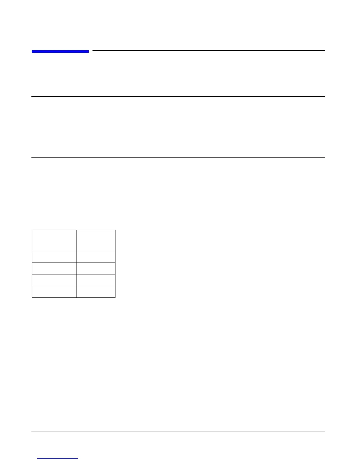
Processors must be installed in a specific order as detailed in Table 4-5. Figure 4-13 shows the processor slot
locations on the processor extender board.
Table 4-5 Processor Load Order
Processor
Modules
Socket
First CPU 0
Second CPU 1
Third CPU 2
Fourth CPU 3
 Loading...


