165
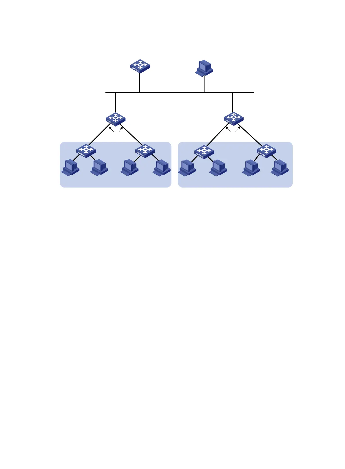
Figure 51 Network diagram
Configuration procedure
1. Configure the DHCP server:
# Create a VLAN interface and assign an IP address to the interface.
<SwitchA> system-view
[SwitchA] vlan 2
[SwitchA-vlan2] port gigabitethernet 1/0/1
[SwitchA-vlan2] quit
[SwitchA] interface vlan-interface 2
[SwitchA-Vlan-interface2] ip address 192.168.1.42 24
[SwitchA-Vlan-interface2] quit
# Enable DHCP.
[SwitchA] dhcp enable
# Enable the DHCP server on VLAN-interface 2.
[SwitchA] interface vlan-interface 2
[SwitchA-Vlan-interface2] dhcp select server
[SwitchA-Vlan-interface2] quit
# Configure the address pool market to assign IP addresses on subnet 192.168.2.0/24 to
clients in the Marketing department. Specify the TFTP server, gateway, and configuration file
name for the clients.
[SwitchA] dhcp server ip-pool market
[SwitchA-dhcp-pool-market] network 192.168.2.0 24
[SwitchA-dhcp-pool-market] tftp-server ip-address 192.168.1.40
[SwitchA-dhcp-pool-market] gateway-list 192.168.2.1
[SwitchA-dhcp-pool-market] bootfile-name market.cfg
[SwitchA-dhcp-pool-market] quit
# Configure the address pool rd to assign IP addresses on subnet 192.168.3.0/24 to clients in
the R&D department. Specify the TFTP server, gateway, and configuration file name for the
clients.
Switch A
DHCP server
Switch B
DHCP relay agent
Marketing
GE1/0/1
GE1/0/2
Vlan-int2
GE1/0/3
192.168.1.41/24
192.168.1.40/24
Switch C
DHCP relay agent
R&D
GE1/0/1 GE1/0/2
TFTP server
Vlan-int2
GE1/0/1
192.168.1.42/24
Vlan-int2
GE1/0/3
192.168.1.43/24
Switch D Switch E Switch F
Switch G
GE1/0/1 GE1/0/1
GE1/0/1 GE1/0/1
Vlan-int3
192.168.2.1/24
Vlan-int3
192.168.3.1/24
…
…
…
…

 Loading...


