109
Patch installation example
Network requirements
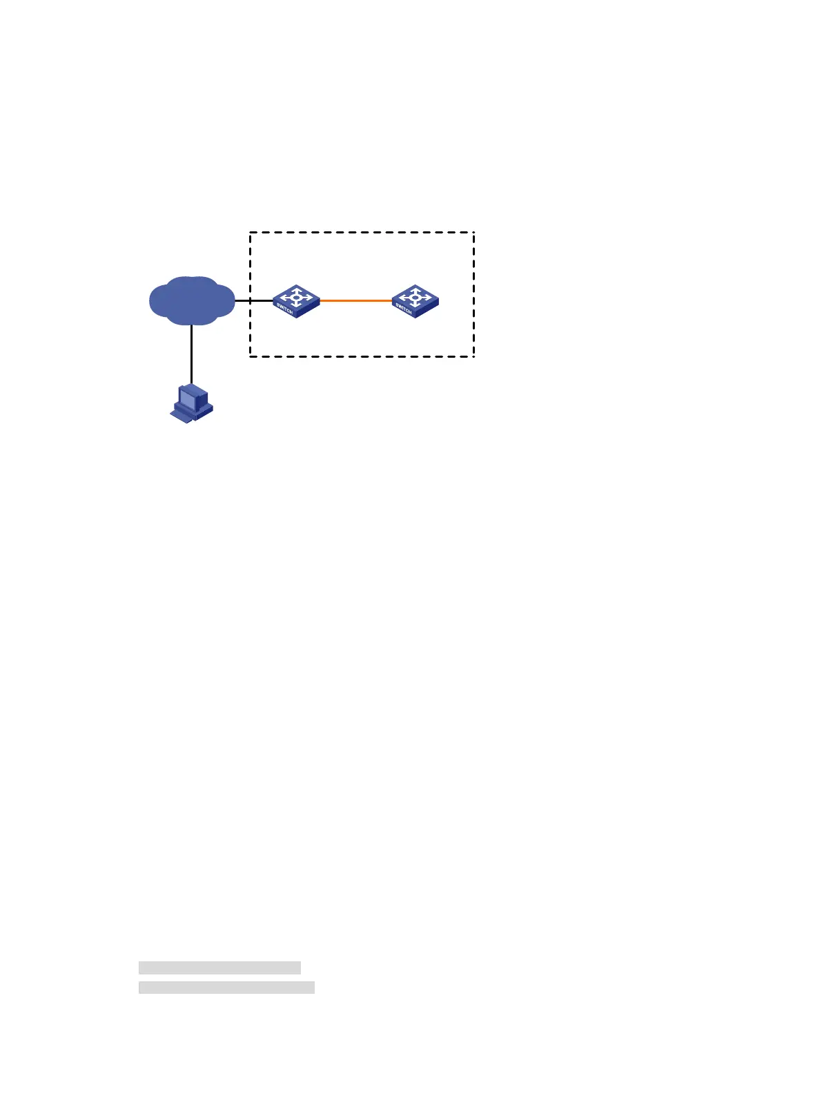
As shown in Figure 34, the IRF fabric has two members.
Patch the software of the switches to fix bugs.
Figure 34 Network diagram
Configuration procedure
# Download the patch images boot-patch.bin and system-patch.bin from the TFTP server to the
root directory of the master's flash memory.
<Sysname> tftp 2.2.2.2 get boot-patch.bin
<Sysname> tftp 2.2.2.2 get system-patch.bin
# Display active software images.
<Sysname> display install active
Active packages on slot 1:
flash:/boot.bin
flash:/system.bin
Active packages on slot 2:
flash:/boot.bin
flash:/system.bin
The patch images boot-patch.bin and system-patch.bin are not on the list.
# Activate the patch images boot-patch.bin and system-patch.bin on the member switches.
<Sysname> install activate patch flash:/boot-patch.bin slot 1
<Sysname> install activate patch flash:/system-patch.bin slot 1
<Sysname> install activate patch flash:/boot-patch.bin slot 2
<Sysname> install activate patch flash:/system-patch.bin slot 2
# Display active images.
<Sysname> display install active
Active packages on slot 1:
flash:/boot.bin
flash:/system.bin
flash:/boot-patch.bin
flash:/system-patch.bin
Active packages on slot 2:
TFTP server
2.2.2.2/24
Internet
IRF
1.1.1.1/24
Note: The orange line represents an IRF connection.
Master
(Member_ID=1)
Subordinate
(Member_ID=2)

 Loading...


