435
Display the MFF configuration information for a VLAN.
display mac-forced-forwarding vlan
vlan-id
MFF configuration examples
Manual-mode MFF configuration example in a tree network
Network requirements
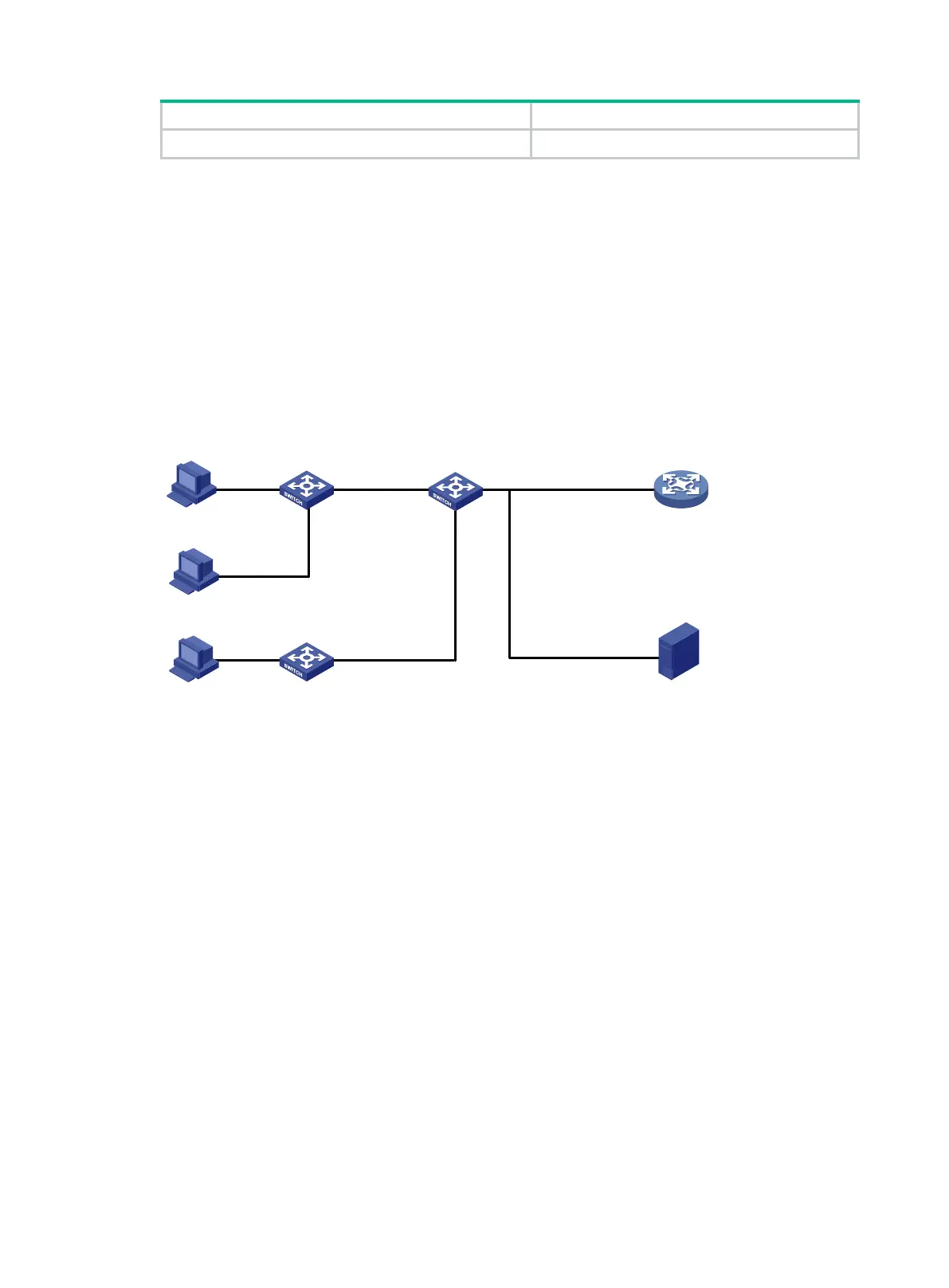
As shown in Figure 131, all the devices are in VLAN 100. Hosts A, B, and C are assigned IP
addresses manually.
Configure MFF to isolate the hosts at Layer 2 and allow them to communicate with each other
through Gateway at Layer 3.
Figure 131 Network diagram
Configuration procedure
1. Configure the IP addresses of the hosts and Gateway as shown in Figure 131.
2. Configure Switch A:
# Configure manual-mode MFF on VLAN 100.
[SwitchA] vlan 100
[SwitchA-vlan100] mac-forced-forwarding default-gateway 10.1.1.100
# Specify the IP address of the server.
[SwitchA-vlan100] mac-forced-forwarding server 10.1.1.200
# Enable ARP snooping on VLAN 100.
[SwitchA-vlan100] arp snooping enable
[SwitchA-vlan100] quit
# Configure GigabitEthernet 1/0/2 as a network port.
[SwitchA] interface gigabitethernet 1/0/2
[SwitchA-GigabitEthernet1/0/2] mac-forced-forwarding network-port
3. Configure Switch B:
# Configure manual-mode MFF on VLAN 100.
[SwitchB] vlan 100
[SwitchB-vlan100] mac-forced-forwarding default-gateway 10.1.1.100
# Specify the IP address of the server.
Switch A
Switch C
Host C
10.1
.1.
3/24
Host B
10.
1.1
.
2/
24
Host A
10.1
.1.1
/24
Gateway
Switch B
GE1
/0/
5
GE1
/0/
6
GE1/
0
/4
GE1/
0/3 GE
1/0
/
2
GE1
/0
/8
GE1
/
0/
7 GE
1
/0
/
1
Server
10.
1.1
.100/
24
10.1
.1.200
/24

 Loading...


