1. When only teamwork communication is required, cascade teamwork communication
ports 1s and 2s of precision air conditioners to be networked. Reserve com 1 of the first
unit, and connect the com 2 of the first unit to com 1 of the second unit. Connect like this.
The "CAN bus" in Figure 3-30.
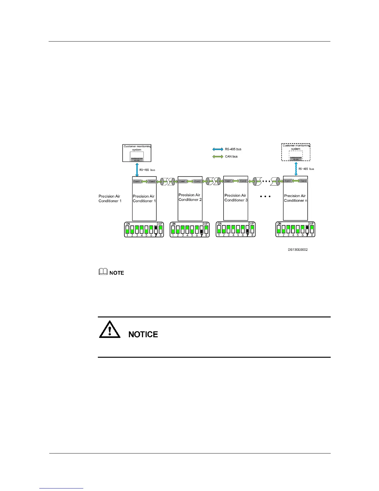
2. When both teamwork communication and communication between precision air
conditioners and the customer monitoring system are required, after cascading teamwork
communication ports 1s and 2s of precision air conditioners to be networked, and
connect teamwork communication port 1 of the first precision air conditioner or the last
precision air conditioner to the RS485 port on the customer monitoring system. The
"RS-485 bus" in Figure 3-30 shows the connection.
Figure 3-30 Networking diagram for the teamwork and communication with the host
The number of precision air conditioners in the preceding figure is less than or equal to 32.
Setting the DIP switchs on the Main Control Board
You need to set only the seventh toggle switch based on site requirements and leave the rest of
toggle switches in their default status.
Figure 3-31 shows the position of the DIP switch of the main control board. Table 3-4 shows
the operations of the DIP switch.