HUAWEI NetEngine40E Universal ServiceRouter
Hardware Description
3 NE40E-X8 Chassis Overview
Huawei Proprietary and Confidential
Copyright © Huawei Technologies Co., Ltd.
Table 3-3 Description of the indicators of the PEM
Indicates normal power output. If the indicator is steady on,
it implies a normal output.
Power failure indicator. If the indicator is steady on, it
indicates the following:
The lightning protection link of the power module has
failed.
The power modules does not have input power.
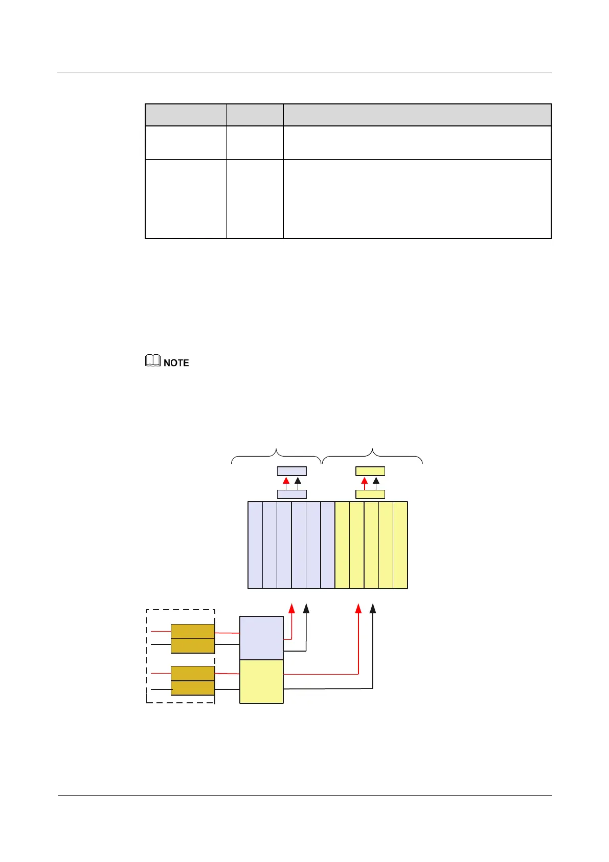
If the NE40E-X8 has a DC power supply system, four 70 A PEMs work in 2+2 backup mode.
Figure 3-7 shows details of the DC power supply system.
Two -48 V power inputs are joined on the board.
After the low-frequency filtering, the two -48 V power inputs for fans Two separated RTN
inputs are joined on the board. inside the fan module.
In Figure 3-7, each DC power input contains one -48 V power input and one RTN input. Two separated
RTN inputs are joined on the board.
Figure 3-7 Architecture of the NE40E-X8 DC power supply system
LPU
LPU
LPU
LPU
LPU
LPU
LPU
LPU
SRU
SRU
SFU
area 1 area 2
area 1
area 2
PEM A1
PEM A2
PEM B1
PEM B2
Boards
backplane
FFU
FAN
FFU
FAN
Table 3-4 lists the technical parameters of the PEM.