Procedure
Step 1 Run the debugging efm interface interface-type interface-number { all | error | event |
message | packet { all | receive | send } | process } command in the user view to enable the
debugging of the EFM OAM module on the specified interface.
----End
4.9 Configuration Examples
This section provides several configuration examples of Ethernet OAM.
4.9.1 Example for Configuring EFM OAM
Networking Requirements
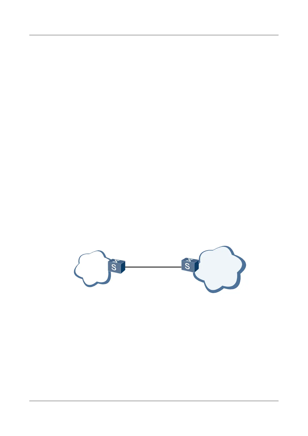
As shown in Figure 4-5, a user network is connected to an ISP network through Switch A and
Switch B. Switch A functions as the CE device, and Switch B functions as the underlayer PE
(UPE) device. The networking requirements are as follows:
l Automatic connectivity detection can be performed between Switch A and Switch B. After
detecting connectivity faults, Switch A and Switch B generate alarms.
l Switch B monitors the errored frames, errored codes, and errored frame seconds on XGE
0/0/1. When the number of errored frames, errored codes, or errored frame seconds exceeds
the threshold, Switch B generates an alarm.
Figure 4-5 Networking diagram for configuring EFM OAM
User
network
Internet
SwitchB
XGE0/0/1XGE0/0/1
SwitchA
Configuration Roadmap
The configuration roadmap is as follows:
1. Enable EFM OAM globally on Switch A and Switch B.
2. Configure EFM OAM on XGE 0/0/1 of Switch A to work in passive mode.
3. Enable EFM OAM on XGE 0/0/1 on Switch B. Enable EFM OAM on XGE 0/0/1 on Switch
A.
4. Configure XGE 0/0/1 of Switch B to detect the errored frames, errored codes, and errored
frame seconds.
Quidway S6700 Series Ethernet Switches
Configuration Guide - Reliability 4 Ethernet OAM Configuration-EFM
Issue 01 (2011-07-15) Huawei Proprietary and Confidential
Copyright © Huawei Technologies Co., Ltd.
173
 Loading...


