6.11.3 Example for Configuring VRRP Fast Switchover
Networking Requirements
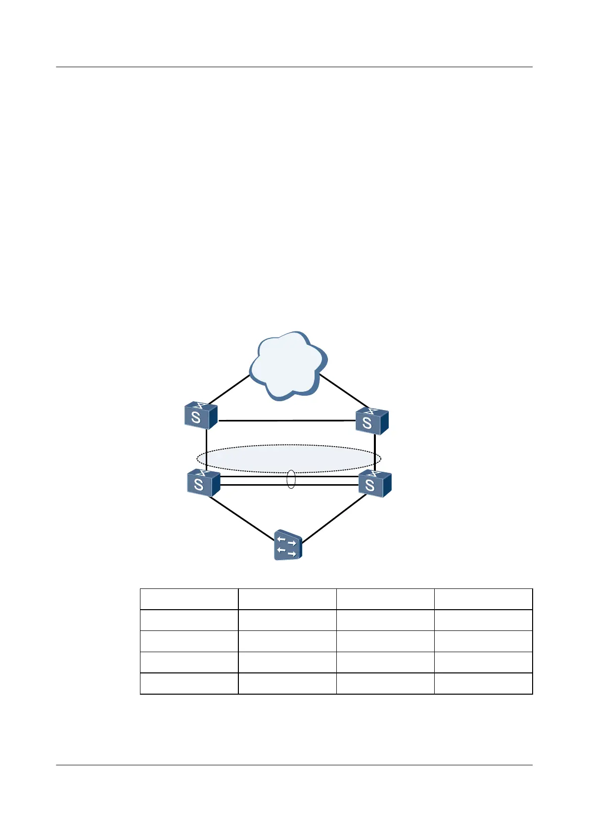
As shown in Figure 6-5, Switch A, Switch B, Switch C, Switch D and the Universal Medium
Gateway (UMG) form a simple next generation network (NGN).
The networking is as follows:
l The UMG connects to Switch A and Switch B through Switch C and Switch D.
l Switch A and Switch B run VRRP. Switch A functions as the master, and Switch B
functions as the backup.
When Switch A fails, or when the link between Switch A and Switch B fails, the active/standby
switchover should be completed within 1 second. That is, fast switchover is required on the
bearer network.
Figure 6-5 Networking of VRRP fast switchover
Backup group 10
Virtual IP address: 10.1.1.3/24
SwitchA
SwitchB
SwitchC
SwitchD
UMG
VLAN
XGE0/0/1
XGE0/0/2
XGE0/0/1
Backbone
Network
XGE0/0/2
Device
Interface VLANIF interface IP address
Switch A XGE 0/0/1 VLANIF100 10.1.1.1/24
XGE 0/0/2 VLANIF200 192.168.0.1/24
Switch B XGE 0/0/1 VLANIF100 10.1.1.2/24
XGE 0/0/2 VLANIF200 192.168.0.2/24
Quidway S6700 Series Ethernet Switches
Configuration Guide - Reliability 6 VRRP and VRRP6 Configuration
Issue 01 (2011-07-15) Huawei Proprietary and Confidential
Copyright © Huawei Technologies Co., Ltd.
259
 Loading...


