3.6.2 Example for Configuring Crossed RRPP Rings with a Single
Instance
Networking Requirements
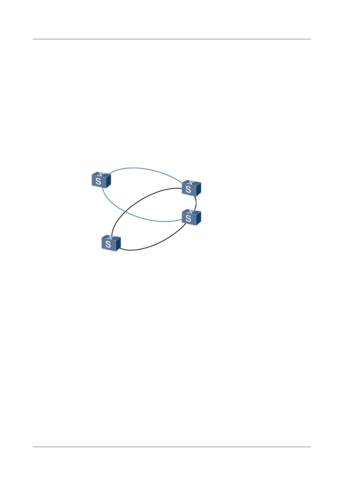
As shown in Figure 3-6, Switch A, Switch B, Switch C, and Switch D support the RRPP
function. Switch A, Switch B, and Switch D are on ring 1 of domain 1, which is the major ring.
Switch A, Switch C, and Switch D are on ring 2 of domain 1, which is the subring. Switch A is
the edge node on ring 2 of domain 1, and Switch D is the assistant edge node on ring 2 of domain
1.
The main control VLAN ID is 10. The RRPP rings transmit data of VLAN 2 to VLAN 9.
Figure 3-6 Networking diagram of crossed RRPP rings with a single instance (Huawei version)
SwitchA
XGE0/0/1
XGE0/0/2
XGE0/0/1
XGE0/0/2
XGE0/0/3
XGE0/0/1
SwitchB
sub-ring
SwitchC
XGE0/0/3
XGE0/0/2
XGE0/0/1
XGE0/0/2
major ring
SwitchD
Configuration Roadmap
The configuration roadmap is as follows:
1. Configure ring 1 (major ring) of domain 1 on Switch A, Switch B, and Switch C. Configure
VLAN 10 as the main control VLAN. Add the interfaces on the major ring and subring to
VLAN 2 to VLAN 9 so that the interfaces allow service packets of these VLANs to pass
through.
2. Configure ring 2 (subring) of domain 1on Switch A, Switch B, and Switch D.
3. Configure Switch B as the master node of the major ring and configure Switch A and Switch
D as transit nodes of the major ring.
4. Configure Switch C as the master node of the subring; configure Switch A as the edge node
of the subring; configure Switch D as the assistant edge node of the subring.
Data Preparation
To complete the configuration, you need the following data.
l Numbers of the interfaces to be added to the RRPP rings
l Control VLAN IDs and data VLAN IDs
Quidway S6700 Series Ethernet Switches
Configuration Guide - Reliability 3 RRPP Configuration
Issue 01 (2011-07-15) Huawei Proprietary and Confidential
Copyright © Huawei Technologies Co., Ltd.
79
 Loading...


