6.11.5 Example for Configuring VRRP6 in Load Balancing Mode
Networking Requirements
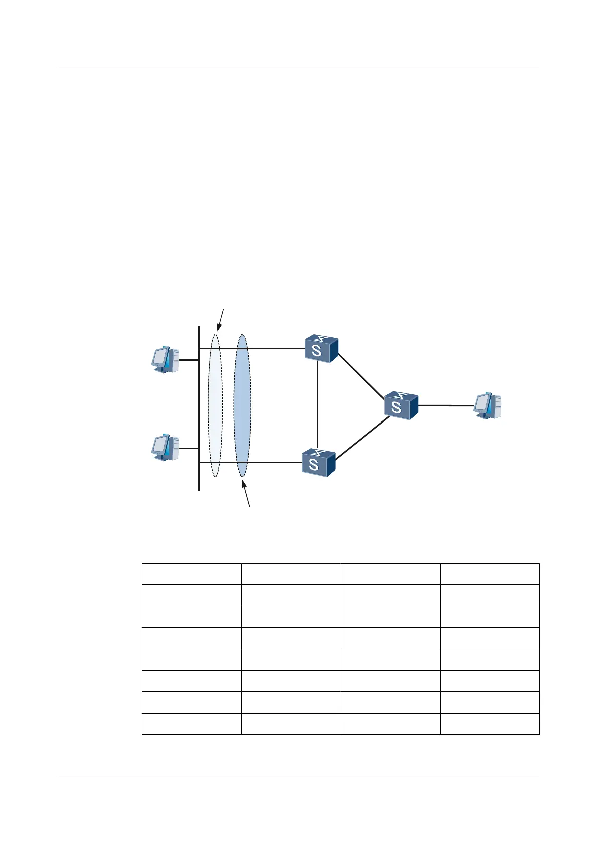
As shown in Figure 6-7,
l Switch A is the master device in VRRP group 1 and the backup device in VRRP group 2.
l Switch B is the master device in VRRP group 2 and the backup device in VRRP group 1.
l Host A on the LAN uses the virtual IPv6 address of VRRP group 1 as the gateway address,
and Host B uses the virtual IPv6 address of VRRP group 2 as the gateway address. The
two VRRP groups load balance traffic and back up each other.
Figure 6-7 Networking of VRRP in load balancing mode
HostA
2000::3/64
XGE0/0/1
XGE0/0/1
Ethernet
SwitchA
group 1:Master
group 2:Backup
XGE0/0/2
XGE0/0/2
XGE0/0/1
XGE0/0/2
XGE0/0/3
HostC
2003::1/64
SwitchC
HostB
2000::4/64
Virtual IP Address
2000::60
Backup group 2
Virtual IP Address
2000::100
Backup group 1
SwitchB
group 1:Backup
group 2:Master
Device
Interface VLANIF interface IP address
Switch A XGE 0/0/1 VLANIF100 2000::1/64
XGE 0/0/2 VLANIF200 2002::1/64
Switch B XGE 0/0/1 VLANIF100 2000::2/64
XGE 0/0/2 VLANIF400 2001::1/64
Switch C XGE 0/0/1 VLANIF200 2002::2/64
XGE 0/0/2 VLANIF400 2001::2/64
XGE 0/0/3 VLANIF300 2003::2/64
Quidway S6700 Series Ethernet Switches
Configuration Guide - Reliability 6 VRRP and VRRP6 Configuration
Issue 01 (2011-07-15) Huawei Proprietary and Confidential
Copyright © Huawei Technologies Co., Ltd.
267
 Loading...


