#
interface XGigabitEthernet 0/0/2
port hybrid tagged vlan 10 to 11
stp disable
#
return
3.6.4 Example for Configuring a Single RRPP Ring with Multiple
Instances
Networking Requirements
As shown in Figure 3-8, UPE A, UPE B, UPE C, and PE-AGG form a multi-instance RRPP
ring.
Two rings are involved in the networking, ring 1 in domain 1 and ring 1 in domain 2.
VLANs 100 to 300 are configured on CE. Domain 1 and domain 2 share the traffic of packets
from VLANs 100 to 300. Packets from VLANs 100 to 200 are transmitted through domain 1,
and packets from VLANs 201 to 300 are transmitted through domain 2.
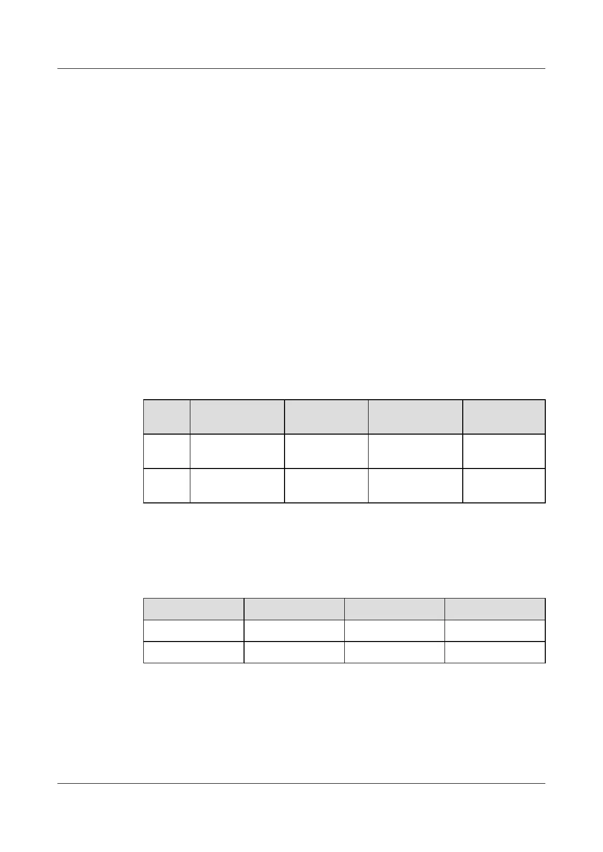
Table 3-1 shows the mapping between protected VLANs and instances in domain 1 and domain
2.
Table 3-1 Mapping between protected VLANs and instances
Ring
ID
Control VLAN
ID
Instance ID of
Control VLAN
Data VLAN ID Instance ID of
Data VLAN
Domain
1
VLAN 5, VLAN 6 Instance 1 VLAN 100-200 Instance 1
Domain
2
VLAN 10, VLAN
11
Instance 2 VLAN 201-300 Instance 2
Table 3-2 shows the master node of each ring, and the primary port and secondary port on the
master node.
Table 3-2 Master nodes, and primary and secondary ports on the master nodes
Ring ID
Master Node Primary Port Secondary Port
Ring 1 in domain 1 PE-AGG XGE0/0/1 XGE0/0/2
Ring 1 in domain 2 PE-AGG XGE0/0/2 XGE0/0/1
Quidway S6700 Series Ethernet Switches
Configuration Guide - Reliability 3 RRPP Configuration
Issue 01 (2011-07-15) Huawei Proprietary and Confidential
Copyright © Huawei Technologies Co., Ltd.
97
 Loading...


