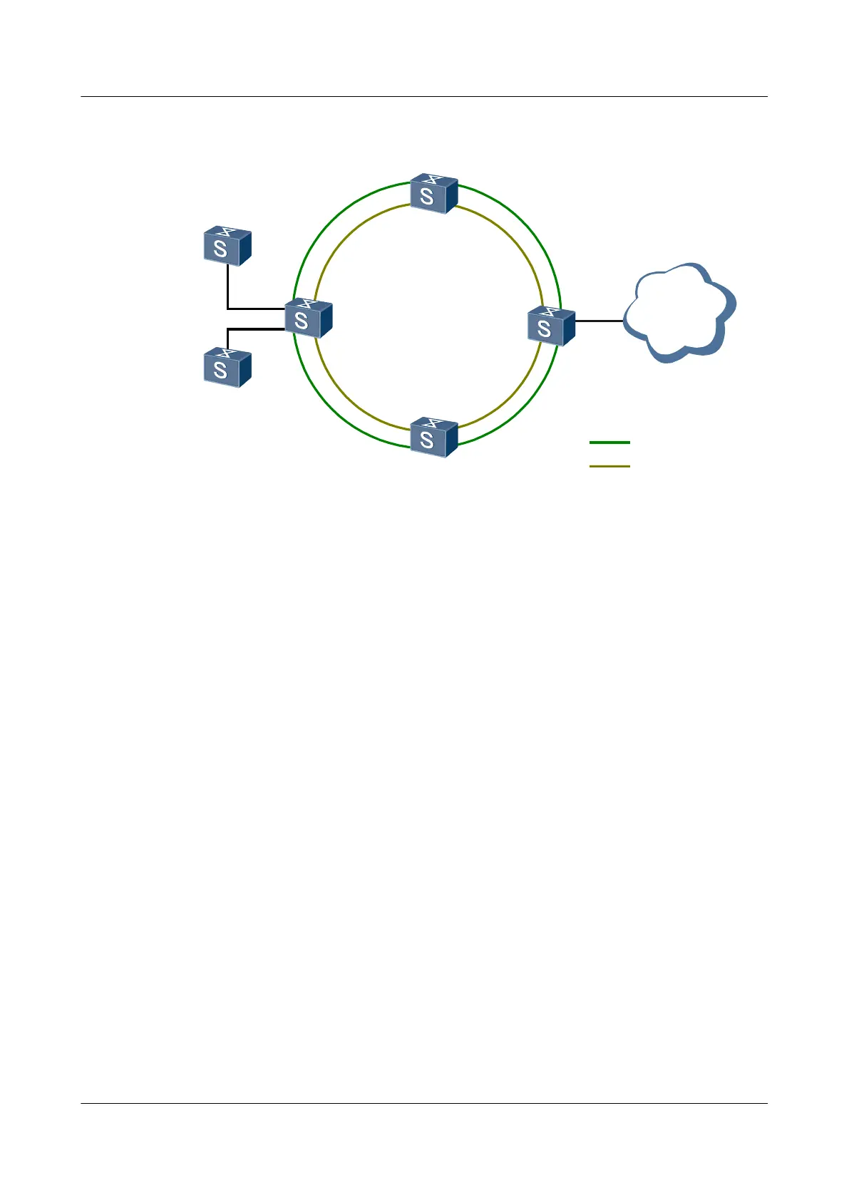
Figure 3-8 Networking diagram of single RRPP ring with multiple instances
UPEA
UPE B
PE-AGG
Domain 2 ring 1
Domain 1 ring 1
UPEC
Master 1
Master 2
Backbone
network
CE 2
CE 1
XGE0/0/1
XGE0/0/2
Ring 1
VLAN 100-300
VLAN 100-300
XGE0/0/1
XGE0/0/1
XGE0/0/1
XGE0/0/2
XGE0/0/2
XGE0/0/2
Configuration Roadmap
The configuration roadmap is as follows:
1. Map instance 1 to VLANs 100 to 200. Map instance 2 to VLANs 201 to 300.
2. Add UPE A, UPE B, UPE C, and PE-AGG to ring 1 in domain 1.
3. Add UPE A, UPE B, UPE C, and PE-AGG to ring 1 in domain 2.
4. Configure protected VLANs in domain 1 and domain 2.
5. Configure control VLANs in domain 1 and domain 2.
6. Configure PE-AGG as the master node on ring 1 in domain 1 and configure UPE A, UPE
B, and UPE C as transit nodes.
7. Configure PE-AGG as the master node on ring 1 in domain 2 and configure UPE A, UPE
B, and UPE C as transit nodes.
Data Preparation
To complete the configuration, you need the following data:
l Instance IDs
l Range of the protected VLANs
l IDs of the control VLANs
l Numbers of the RRPP interfaces
Procedure
Step 1 Create instances.
Quidway S6700 Series Ethernet Switches
Configuration Guide - Reliability 3 RRPP Configuration
Issue 01 (2011-07-15) Huawei Proprietary and Confidential
Copyright © Huawei Technologies Co., Ltd.
98
 Loading...


