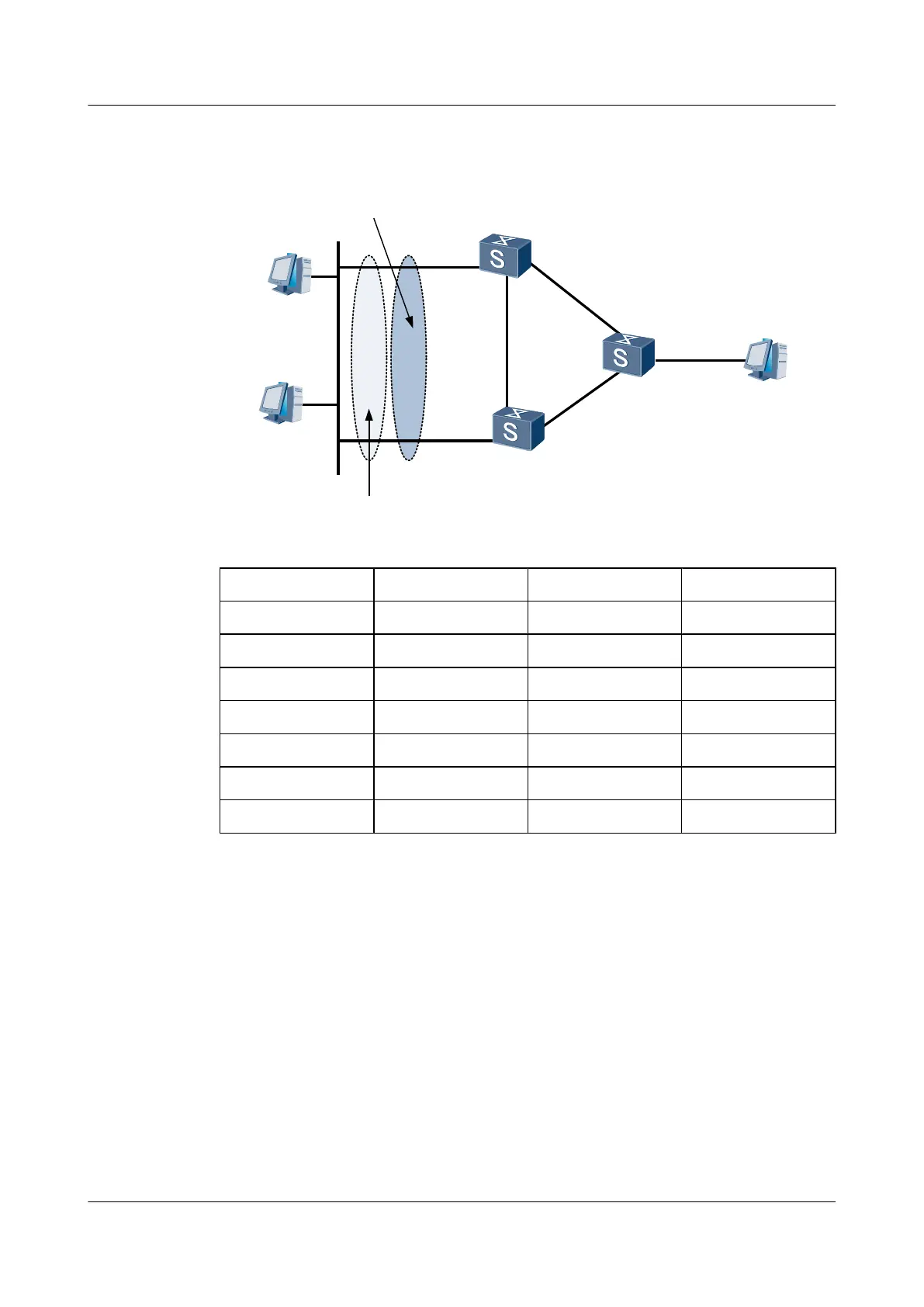
Figure 6-4 Networking of VRRP in load balancing mode
20.1.1.100/24
SwitchB
group 1:Backup
group 2:Master
Backup group 2
Virtual IP Address:
10.1.1.112
Backup group 1
Virtual IP Address:
10.1.1.111
Ethernet
HostA
10.1.1.100/24
XGE0/0/2
XGE0/0/3
XGE0/0/1
HostB
SwitchC
XGE0/0/2
XGE0/0/2
SwitchA
group 1:Master
group 2:Backup
HostC
10.1.1.101/24
XGE0/0/1
XGE0/0/1
Device Interface VLANIF interface IP address
Switch A XGE 0/0/1 VLANIF100 10.1.1.1/24
XGE 0/0/2 VLANIF200 192.168.1.1/24
Switch B XGE 0/0/1 VLANIF100 10.1.1.2/24
XGE 0/0/2 VLANIF400 192.168.2.1/24
Switch C XGE 0/0/1 VLANIF300 20.1.1.1/24
XGE 0/0/2 VLANIF200 192.168.1.2/24
XGE 0/0/3 VLANIF400 192.168.2.2/24
Configuration Roadmap
The configuration roadmap is as follows:
1. Implement networking between Switch A, Switch B, and Switch C.
2. Create two VRRP groups on VLANIF 100 of Switch A. Configure Switch A as the master
device in VRRP group 1 and the backup device in VRRP group 2.
3. Create two VRRP groups on VLANIF 100 of Switch B. Configure Switch B as the master
device in VRRP group 2 and the backup device in VRRP group 1.
Data Preparation
To complete the configuration, you need the following data:
Quidway S6700 Series Ethernet Switches
Configuration Guide - Reliability 6 VRRP and VRRP6 Configuration
Issue 01 (2011-07-15) Huawei Proprietary and Confidential
Copyright © Huawei Technologies Co., Ltd.
255
 Loading...


