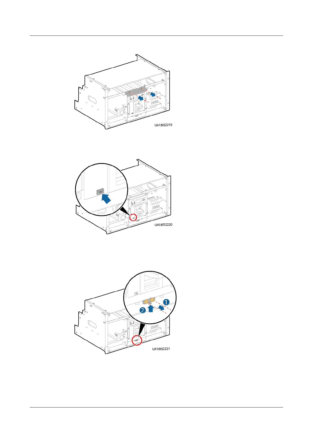
Figure 8-3 Removing the clamping plate from the top of the switch
Step 3 Press the TEST button on the switch to ensure that the switch trips.
Figure 8-4 Pressing the TEST button
Step 4 Remove the two screws from the bottom of the switch and keep them properly.
Then push the bottom fastener upwards.
Figure 8-5 Pushing the bottom fastener upwards
Step 5 Insert the assisting tool into the big positioning holes in the subrack.
UPS5000-E-(30 kVA–180 kVA)
User Manual (Integrated UPS) 8 Parts Replacement
Issue 02 (2022-12-30) Copyright © Huawei Digital Power Technologies Co., Ltd. 158