100
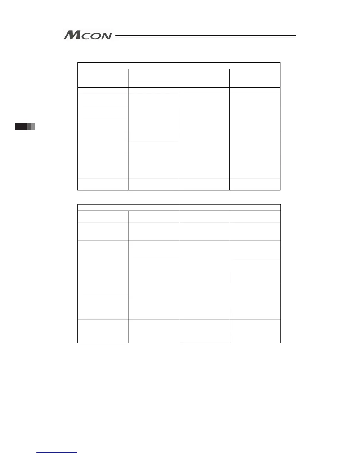
3) PROFIBUS-DP, EtherNet/IP, EtherCAT
(n is the top node address for each PLC input and output between MCON and PLC)
PLC → MCON MCON → PLC
Node Address
(Byte Address)
Description
Node Address
(Byte Address)
Description
n to n+3 Gateway Control n to n+3 Gateway Status
n+4 to n+15 Demand Command n+4 to n+15 Response Command
n+16 to n+19
Axis No.0 Control
Information
n+16 to n+19
Axis No.0 Status
Information
n+20 to n+23
Axis No.1 Control
Information
n+20 to n+23
Axis No.1 Status
Information
n+24 to n+27
Axis No.2 Control
Information
n+24 to n+27
Axis No.2 Status
Information
n+28 to n+31
Axis No.3 Control
Information
n+28 to n+31
Axis No.3 Status
Information
n+32 to n+35
Axis No.4 Control
Information
n+32 to n+35
Axis No.4 Status
Information
n+36 to n+39
Axis No.5 Control
Information
n+36 to n+39
Axis No.5 Status
Information
n+40 to n+43
Axis No.6 Control
Information
n+40 to n+43
Axis No.6 Status
Information
n+44 to n+47
Axis No.7 Control
Information
n+44 to n+47
Axis No.7 Status
Information
4) PROFINET-IO
PLC → MCON MCON → PLC
4-word
Number of Module
Description
4-word
Number of Module
Description
1
Gateway Control,
Demand Command,
Data 0
1
Gateway Status,
Response Command,
Data 0
2 Data 1 to 3 2 Data 1 to 3
Axis No.0 Control
Information
Axis No.0 Status
Information
3
Axis No.1 Control
Information
3
Axis No.1 Status
Information
Axis No.2 Control
Information
Axis No.2 Status
Information
4
Axis No.3 Control
Information
4
Axis No.3 Status
Information
Axis No.4 Control
Information
Axis No.4 Status
Information
5
Axis No.5 Control
Information
5
Axis No.5 Status
Information
Axis No.6 Control
Information
Axis No.6 Status
Information
6
Axis No.7 Control
Information
6
Axis No.7 Status
Information
3.4 Fieldbus Type Address Map

 Loading...


