88
[1] Address Map with Combination of Simple Direct Mode/Positioner 1 Mode and
Direct Indication Mode
In the table below, shows the address map when eight axes of MCON are operated with a
combination of Simple Direct Mode/Positioner 1 Mode and Direct Indication Mode in four
types of construction for each Fieldbus as an example.
Combination
Example
Number of Simple Direct
Mode Axes
Number of Direct Indication
Mode Axes
1 8 0
2 6 2
3 2 6
4 0 8
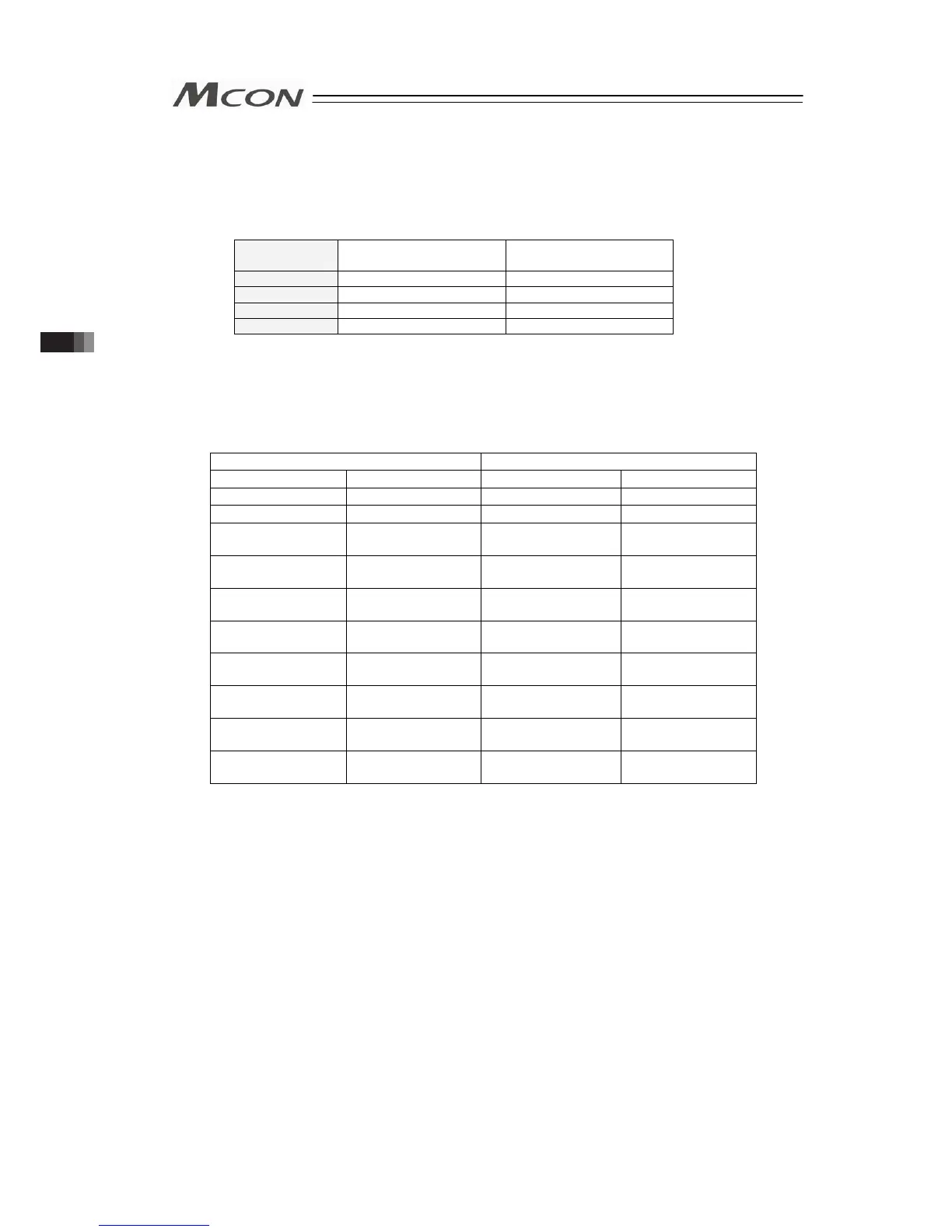
1) DeviceNet (CompoNet is not applicable for this mode)
[Combination Example 1] When number of Simple Direct Mode/Positioner 1 Mode axes is
8 and number of Direct Indication Mode 0
(n is the top channel number for each PLC input and output
between MCON and PLC)
PLC → MCON MCON → PLC
CH No. Description CH No. Description
n to n+1 Gateway Control n to n+1 Gateway Status
n+2 to n+7 Demand Command n+2 to n+7 Response Command
n+8 to n+11
Axis No.0 Control
Information
n+8 to n+11
Axis No.0 Status
Information
n+12 to n+15
Axis No.1 Control
Information
n+12 to n+15
Axis No.1 Status
Information
n+16 to n+19
Axis No.2 Control
Information
n+16 to n+19
Axis No.2 Status
Information
n+20 to n+23
Axis No.3 Control
Information
n+20 to n+23
Axis No.3 Status
Information
n+24 to n+27
Axis No.4 Control
Information
n+24 to n+27
Axis No.4 Status
Information
n+28 to n+31
Axis No.5 Control
Information
n+28 to n+31
Axis No.5 Status
Information
n+32 to n+35
Axis No.6 Control
Information
n+32 to n+35
Axis No.6 Status
Information
n+36 to n+39
Axis No.7 Control
Information
n+36 to n+39
Axis No.7 Status
Information
3.4 Fieldbus Type Address Map