2. Installation
2.3.2 Installation of the Main Unit
The surface to mount the main unit should be a machined surface or a plane that possesses an
equivalent accuracy and the flatness should be within 0.05mm/m. Also, the platform should have a
structure stiff enough to install the unit so it would not generate vibration or other abnormality.
Also consider enough space necessary for maintenance work such as actuator replacement and
inspection.
T-slots are provided on the back of the actuator.
Nut holes are provided on the actuator frame front and the side-mounted motor type rear bracket.
Using these parts, the following installations can be realized.
· Installation by using T-slots
· Installation by using foot brackets (option: model FT)
· Installing main unit frame front
· Installation by using flange (option: model FL)
· Installation by using rear bracket for side-mounted motor types
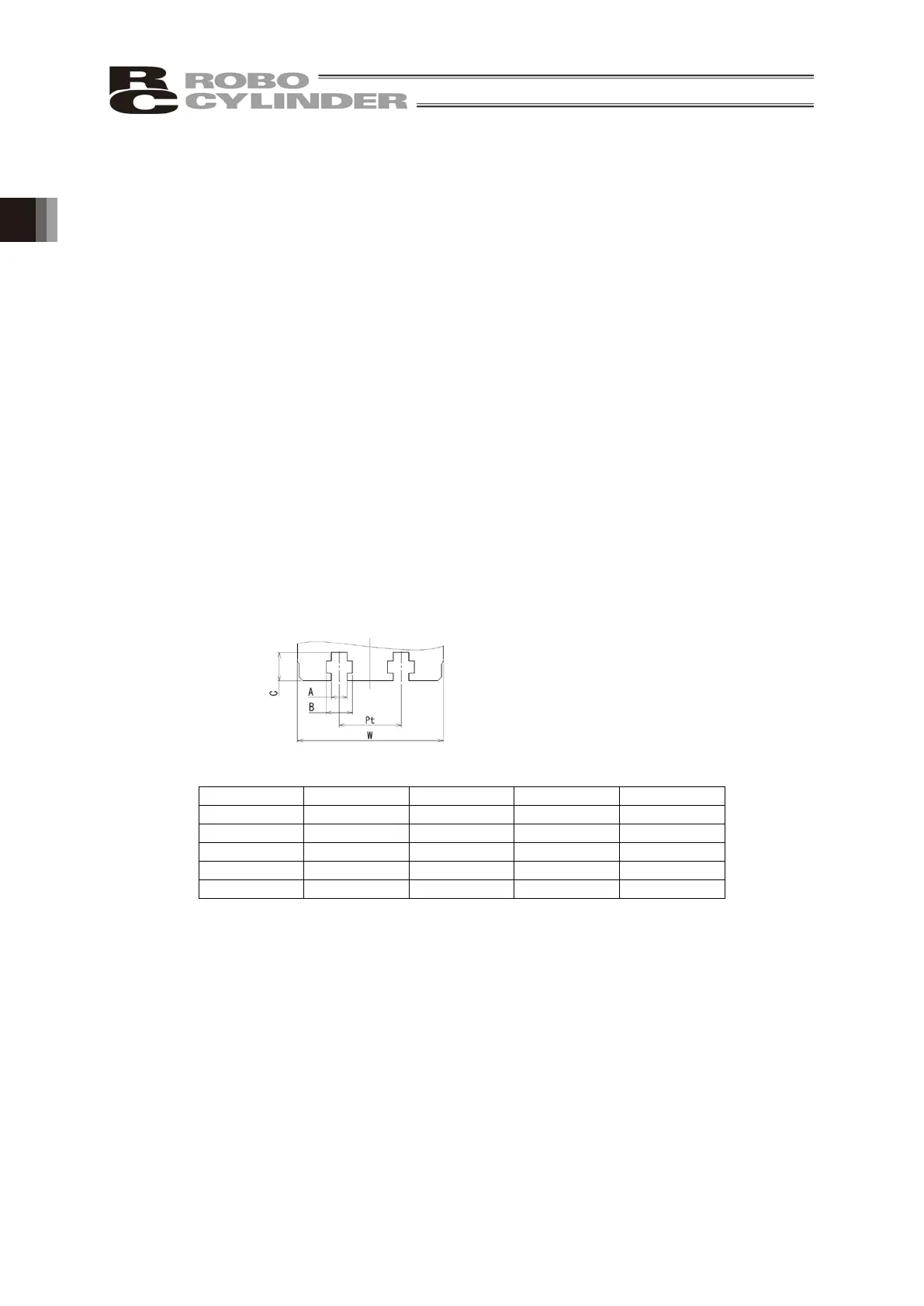
[1] Using the T-slot on the Bottom of the Base
This actuator has T-slot for mounting so it can be fixed from the bottom of the base.
There are two methods of installation: using square T-nuts into T-slots or using optional T-slot nut
bars (model: NTB).
(1) T-slots Dimensions

 Loading...


