2. Wiring
132
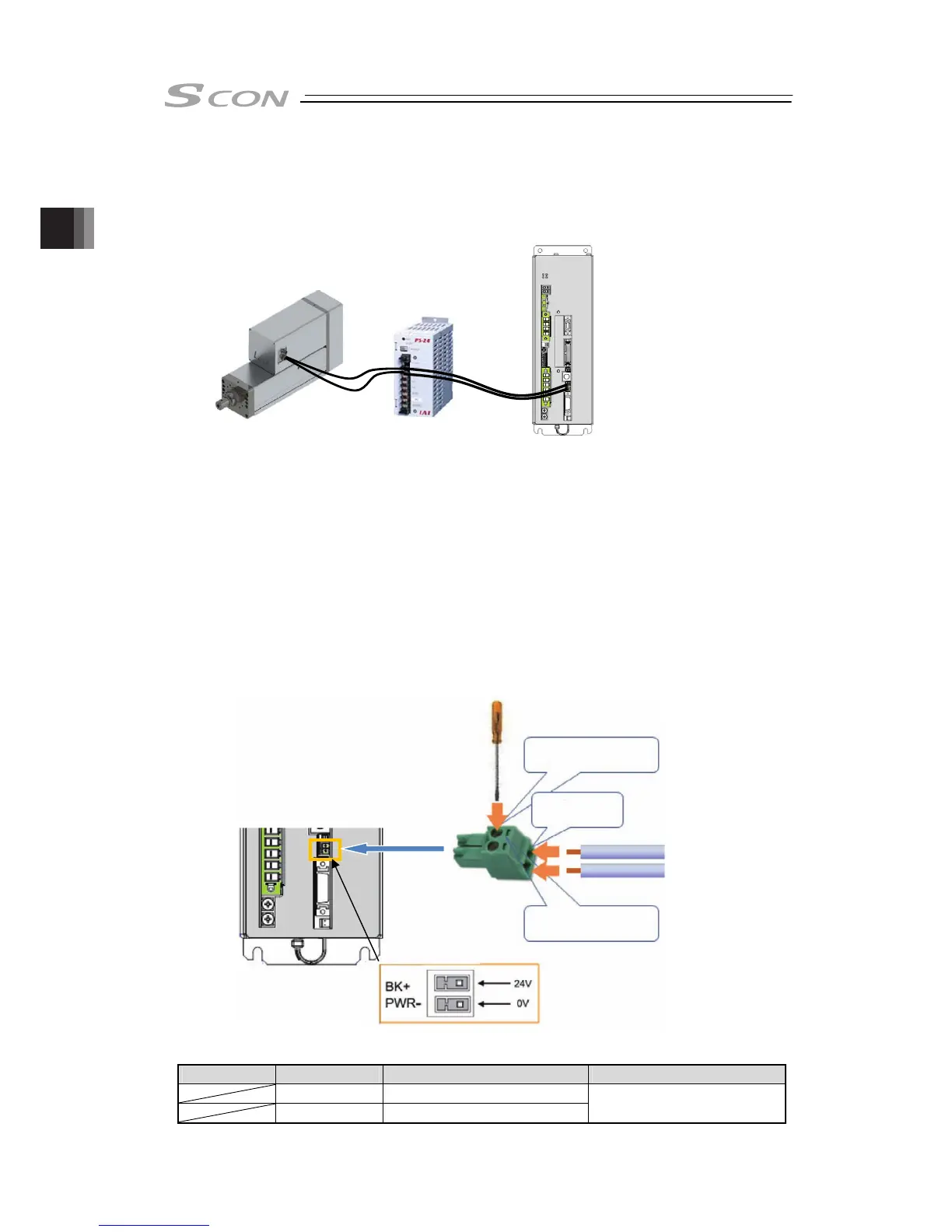
2.6.1.2 Brake Power Supply (Brake Power Connector)
Supply 24V DC ±10% and 0.1A at maximum to the controller and 24V DC ±10% and 1.5A at
maximum to the actuator when an actuator equipped with a brake is used.
● Image of Wiring
● Wiring Method
Connect the power supply to the enclosed connector * (Model code: MC1.5/2-ST-3.5: Phoenix
Contact).
* Controller side : Model code : MC1.5/2-ST-3.5: Phoenix Contact
Actuator side : Model code : FMC1.5/3-STF-3.5: Phoenix Contact
See below for how to lay out the power supply wires.
1) Loosen the terminal screw with using such as a slotted screwdriver to open up the inlet.
2) Reveal the sheath for 7mm (controller side) and 10mm (actuator side) on the cable that
satisfies the cable diameter complies the specification shown in the table below and put it in
the inlet.
3) Tighten the terminal screw with using such as a slotted screwdriver. The inlet closes and
affixes the wire.
4) Connect all the wires in the same manner and insert the enclosed connector to the power
connector.
Brake Power Supply Connector on Controller Side
Pin No. Signal name Items Applicable cable diameter
BK+ 24V DC power input
PWR- 24V DC ground
1.25 to 0.5mm
2
(AWG16 to 20)
24VDC Power
(Please prepare
separately)
1) Loosen the screw with a
slotted screwdriver
3) Tighten the screw with
a slotted screwdriver
2) Insert wire
24V
0V

 Loading...


