8. Parameter
279
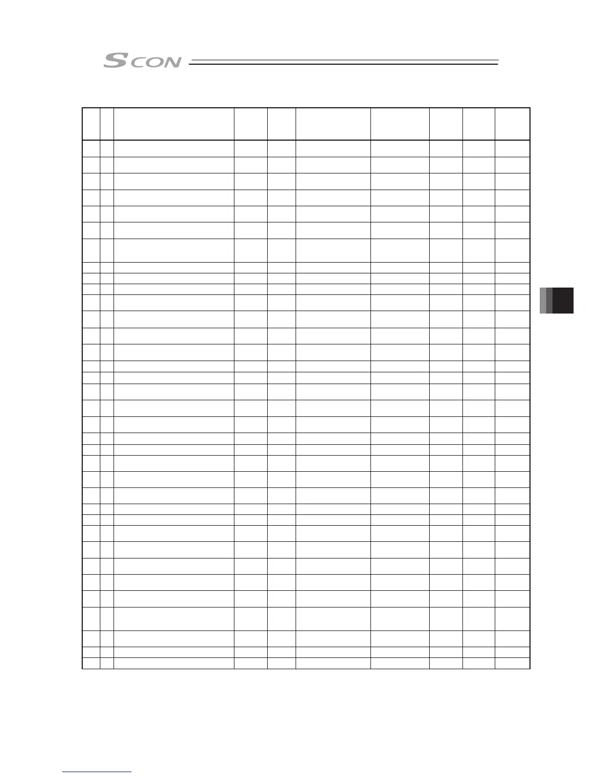
I/O Parameter List (Continued)
No.
Category
Name Symbol
Unit
(Note1)
Input Range
Default factory
setting
for
Positioner
Mode
for Pulse
Train
Mode
Relevant
sections
26 B PIO jog velocity IOJV
mm/s
(deg/s)
1 to Actuator’s
max. speed
100
{
8.2 [21]
27 B Movement command type FPIO –
0: Level
1: Edge
0
{
8.2 [22]
31 C Velocity loop proportional gain VLPG – 1 to 9999999
In accordance with
actuator
(Note2)
{ {
8.2 [23]
8.3
32 C Velocity loop integral gain VLPT – 1 to 9999999
In accordance with
actuator
(Note2)
{ {
8.2 [24]
8.3
33 C Torque filter time constant TRQF – 0 to 2500
In accordance with
actuator
(Note2)
{ {
8.2 [25]
8.3
34 C Press velocity PSHV
mm/s
(deg/s)
1 to actuator's
max. pressing speed
In accordance with
actuator
(Note2)
{
8.2 [26]
35 C Safety velocity SAFV
mm/s
(deg/s)
1 to 250
(max. for actuator of 250
or less)
100
{ {
8.2 [27]
36 B Auto Servo-motor OFF delay time 1 ASO1 sec 0 to 9999 0
{
8.2 [28]
37 B Auto Servo-motor OFF delay time 2 ASO2 sec 0 to 9999 0
{
8.2 [28]
38 B Auto Servo-motor OFF delay time 3 ASO3 sec 0 to 9999 0
{
8.2 [28]
39 B
Position complete signal output method
(Note3)
FPIO – 0: PEND, 1: INP 0
{
8.2 [29]
40 C Home-return input disable FPIO –
0: Enabled,
1: Disabled
0
{ {
8.2 [30]
41 C Operating-mode input disable FPIO –
0: Enabled,
1: Disabled
0
{ {
8.2 [31]
42 C Enable function FPIO –
0: Enabled,
1: Disabled
1
{ {
8.2 [32]
45 B Silent interval magnification SIVM time 0 to 10 0
{ {
8.2 [33]
46 B Velocity override OVRD % 1 to 100 100
{
8.2 [34]
47 B PIO jog velocity 2 IOV2
mm/s
(deg/s)
1 to Actuator’s max.
speed
100
{
8.2 [21]
48 B PIO inch distance IOID
mm
(deg)
0.01 to 1.00 0.1
{
8.2 [36]
49 B PIO inch distance 2 IOD2
mm
(deg)
0.01 to 1.00 0.1
{
8.2 [36]
50 C Load output judgment time period LDWT msec 0 to 9999 255
{
8.2 [37]
52 B Default acceleration/deceleration mode CTLF – 0 to 2 0 (Trapezoid)
{ {
8.2 [38]
53 B Default stop mode CTLF – 0 to 3
0
(Not Applicable)
{
8.2 [39]
54 C Current-control width number CLPF – 0 to 15
In accordance with
actuator
(Note2)
{ {
8.2 [40]
55 B
Position-command primary filter time
constant
PLPF msec 0.0 to 100.0 0.0
{ {
8.2 [41]
56 B S-motion rate SCRV % 0 to 100 0
{
8.2 [42]
57 B Torque limit TQLM % 0 to 70 70
{
3.3.6
58 E
Deviation clear at servo OFF &
alarm stop
FSTP –
0: Disabled,
1: Enabled
1
{
3.3.6
59 C
Deviation error monitor during torque
limiting
FSTP –
0: Disabled,
1: Enabled
0
{
3.3.6
60 B Deviation Counter Clear Input FPIO –
0: Enabled,
1: Disabled
0
{
3.3.6
61 B Torque limit command input FPIO –
0: Enabled,
1: Disabled
0
{
3.3.6
62 B Pulse count direction FPIO –
0: Forward motor rotation
1: Reverse motor rotation
In accordance with
actuator
(Note2)
{ {
3.3.6
63 B
Command pulse input mode
(Pulse string mode)
CPMD – 0 to 2
1 (pulse-train and
moving direction
angle)
{
3.3.4
64 B Command pulse input mode polarity CPMD –
0: Positive Logic
1: Negative Logic
0
{
3.3.4
65 B Electronic gear numerator CNUM –
1 to 99999999
(Note 5)
2048
{ {
3.3.4
66 B Electronic gear denominator CDEN –
1 to 99999999
(Note 5)
125
{ {
3.3.4
Note 1 The unit (deg) is for rotary actuator. It is displayed in mm in the teaching tools.
Note 2 The setting values vary in accordance with the specification of the actuator. At shipment, the
parameters are set in accordance with the specification.
Note 3 In the pulse-train mode, INP is automatically selected. (Cannot be selected)
Note 5 The input range is from 1 to 4096 if the controller version is earlier than V0005.

 Loading...


