8. Parameter
281
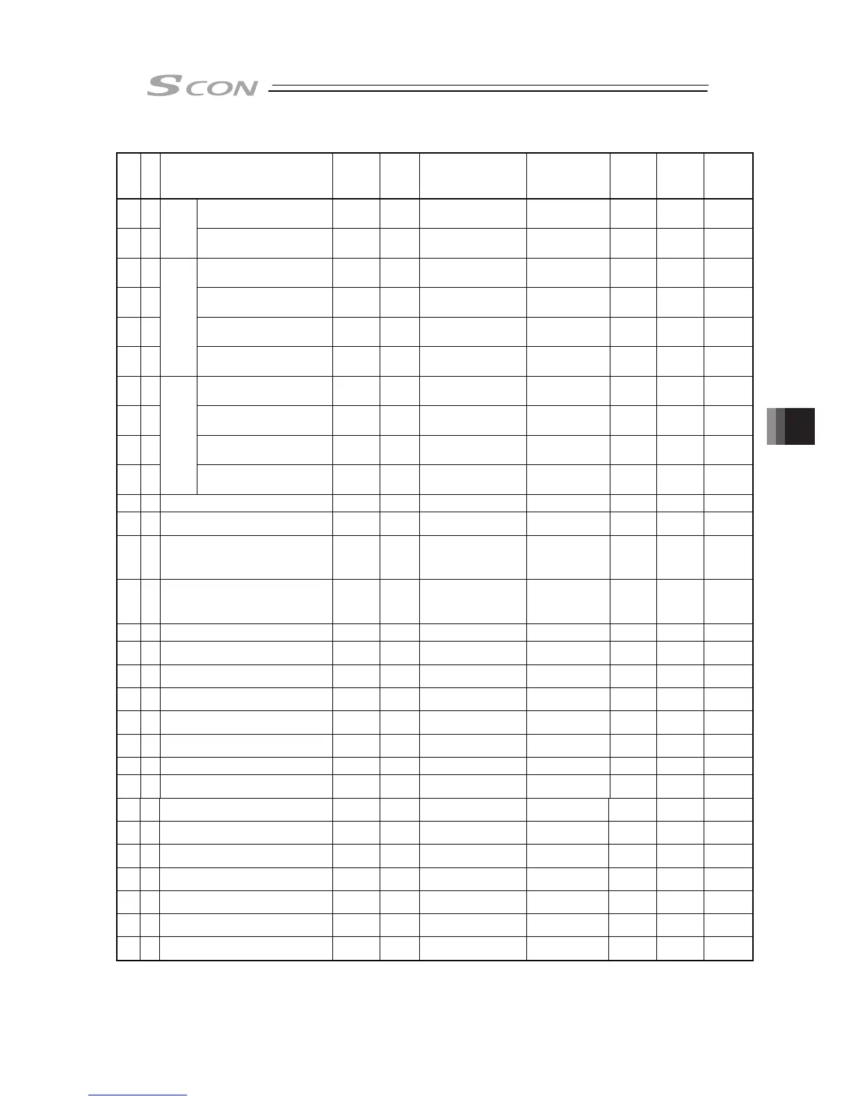
I/O Parameter List (Continued)
No.
Category
Name Symbol Unit Input Range
Default factory
setting
for
Positioner
Mode
for Pulse
Train
Mode
Relevant
sections
99 B Natural frequency NP01
1/1000Hz
500 to 30000 10000
{
5.2
100 C
Vibration
suppress
parameter set 1
Notch filter gain NFG1 – 1 to 20000 9990
{
5.2
101 C
Damping characteristic
coefficient 1
DC12 – 0 to 1000 10
{
5.2
102 C
Damping characteristic
coefficient 2
DC22 – 0 to 1000 1000
{
5.2
103 B Natural frequency NP02
1/1000Hz
500 to 30000 10000
{
5.2
104 C
Vibration suppress
parameter set 2
Notch filter gain NFG2 – 1 to 20000 9990
{
5.2
105 C
Damping characteristic
coefficient 1
DC11 – 0 to 1000 10
{
5.2
106 C
Damping characteristic
coefficient 2
DC21 – 0 to 1000 1000
{
5.2
107 B Natural frequency NP01
1/1000Hz
500 to 30000 10000
{
5.2
108 C
Vibration suppress
parameter set 3
Notch filter gain NFG2 – 1 to 20000 9990
{
5.2
109 B Default vibration suppress No. CTLF – 0 to 3 0
{
5.2
110 B Stop method at servo OFF FSTP –
0: Rapid stop
1: Deceleration to stop
0
{
5.2
111 B Calendar function FRTC –
0: Does not use the
calendar timer
1: Use the calendar
timer
1
{ {
8.2 [82]
112 B Monitoring mode FMNT –
0: Does not use
1: Monitor function 1
2: Monitor function 2
3: Monitor function 3
1
{ {
8.2 [83]
113 B Monitoring period FMNT msec 1 to 1000 1
{ {
8.2 [84]
114 B Selecting used feedback pulse gear ratio FPIO –
0: Not Applicable
1: Use
0
{ {
8.2 [85]
115 B
Electronic gear numerator
(Feedback Pulse)
FNUM –
1 to 99999999
(Note 5)
125
{ {
8.2 [86]
116 B
Electronic gear denominator
(Feedback Pulse)
FDEN –
1 to 99999999
(Note 5)
2048
{ {
8.2 [86]
117 B Automatic loadcell calibration at start FFRC –
0: Does not perform
1: Perform
1
{
8.2 [87]
118 B
Pressing operation without completion of
loadcell calibration
FFRC –
0: Forbidden,
1: Allow
0
{
8.2 [88]
119 B Loadcell calibration time CLBT msec 1 to 9999 10
{
8.2 [89]
120 C Servo gain number 1 PLG1 – 0 to 31
In accordance
with actuator
(Note2)
{
8.2 [5]
8.3
121 C Feed forward gain 1 PLF1 – 0 to 100
In accordance
with actuator
(Note2)
{
8.2 [57]
122 C Velocity loop proportional gain 1 VLG1 – 1 to 9999999
In accordance
with actuator
(Note2)
{
8.2 [23]
8.3
123 C Velocity loop integral gain 1 VLT1 – 1 to 9999999
In accordance
with actuator
(Note2)
{
8.2 [24]
8.3
124 C Torque filter time constant 1 TRF1 – 0 to 2500
In accordance
with actuator
(Note2)
{
8.2 [25]
8.3
125 C Current control width number 1 CLP1 – 0 to 4
In accordance
with actuator
(Note2)
{
8.2 [40]
8.3
126 C Servo gain number 2 PLG2 – 0 to 31
In accordance
with actuator
(Note2)
{
8.2 [5]
8.3
127 C Feed forward gain 2 PLF2 – 0 to 100
In accordance
with actuator
(Note2)
{
8.2 [57]
Note 2: The setting values vary in accordance with the specification of the actuator. At shipment, the
parameters are set in accordance with the specification.
Note 5 The input range is from 1 to 4096 if the controller version is earlier than V0005.

 Loading...


