7-8 Chapter 7: Adding and removing adapter cards and drives
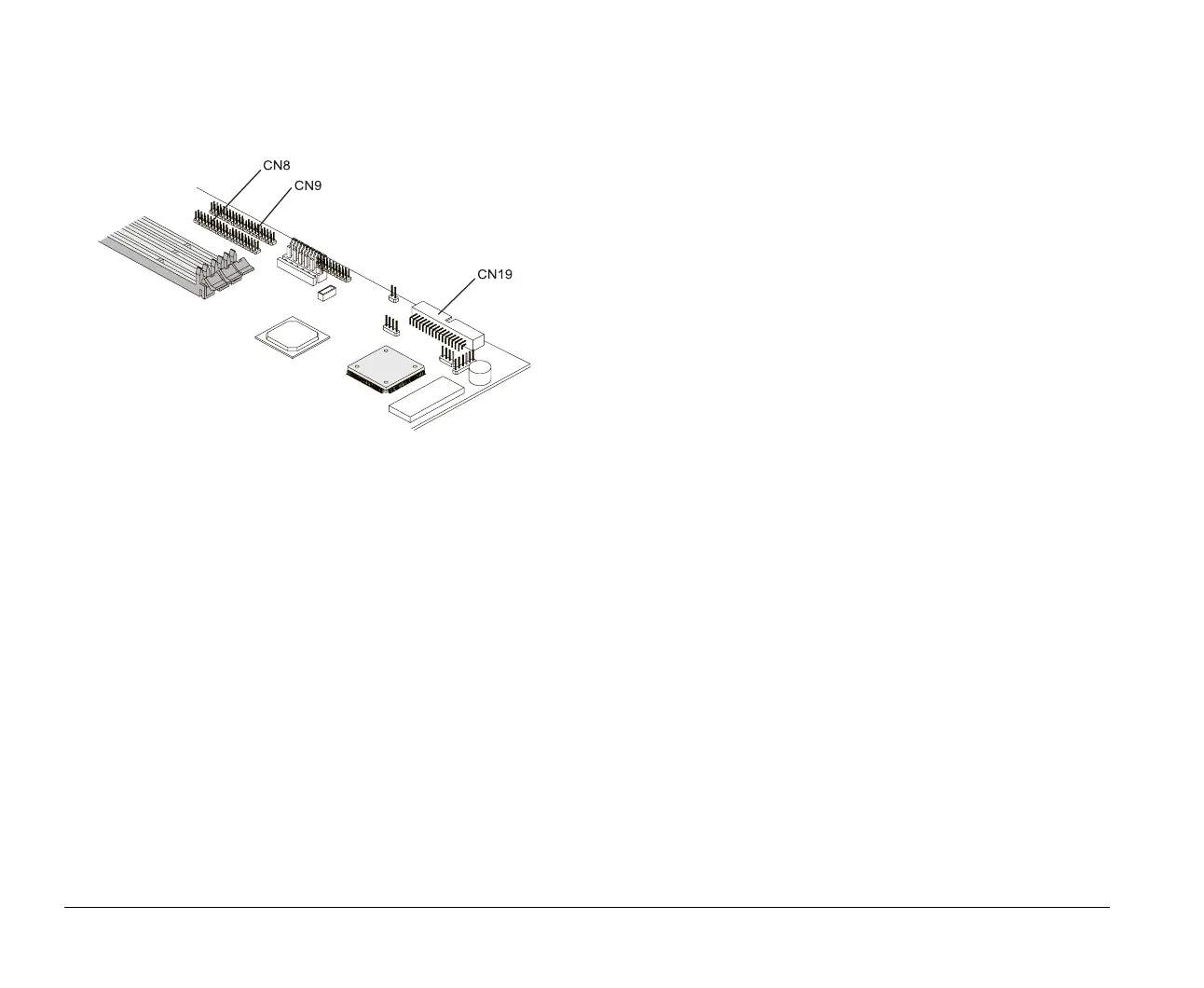
Use the following illustration to identify the signal cable
connectors on your system board:
When attaching a drive signal cable to any of these
connectors, take note of the pin 1 indicator (usually marked
by colored stripes or dots) on the cable to ensure that it
matches the pin 1 on the connector.
Guidelines for connecting IDE/ATA
signal cables
Your system board has two connectors for attaching IDE/ATA
signal cables, but you can install two IDE/ATA drives to each
of these connectors if you have the proper cables. When two
drives are attached to one connector, one drive must be the
master device, and the other the slave device. Jumper
settings on the drives determine which drive is the master
and which is the slave.
The hard disk that came installed in your computer is
attached to IDE connector 1 and is set as a master device. If
your computer came with a CD-ROM drive, it is attached to
IDE connector 2 and is set as a slave device.
These are the general guidelines for IDE/ATA signal cable
connections:
If only one drive is attached to a connector, it typically
must be set as a master device.
On each connector, there can be only one drive set as
the master device and one drive set as the slave device.
A maximum of four IDE drives can be attached to your
computer, two on the primary IDE connector, and two on
the secondary IDE connector.
If a hard disk shares the same connector with a drive
that requires a software device driver (such as a
CD-ROM drive), the hard disk must be set as the master
device.
v65xahb.book : chap-7.fm Page 8 Friday, January 16, 1998 4:27 PM

 Loading...


