54 IBM z13s Technical Guide
2.4.1 Memory subsystem topology
The z13s memory subsystem uses high speed, differential-ended communications memory
channels to link a host memory to the main memory storage devices.
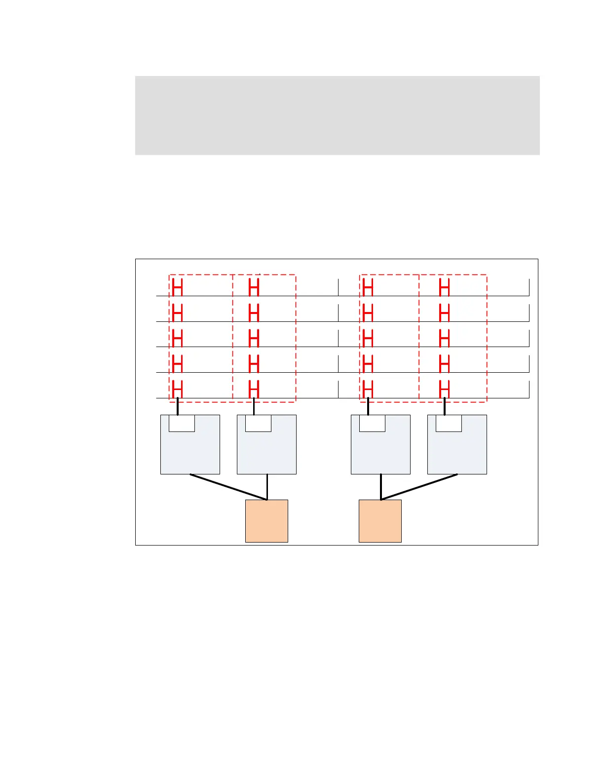
Figure 2-17 shows an overview of the CPC drawer memory topology of a z13s server.
Figure 2-17 CPC drawer memory topology
Each CPC drawer has up to 20 DIMMs. DIMMs are connected to each PU chip through the
MCUs. Each PU chip has one MCU, which uses five channels, one for each DIMM and one
for RAIM implementation, in a 4 +1 design.
Each DIMM can be 16 GB, 32 GB, 64 GB, or 128 GB. DIMM sizes cannot be mixed in the
same CPC drawer, but a two CPC drawer Model N20 can have different (but not mixed) DIMM
sizes in each drawer.
Note: The required granularity for all main storage fields of an LPAR for which an origin
has been specified (for example, initial main storage amount, reserved main storage
amount, and main storage origin) is fixed at 2 GB. This configuration helps to simplify
customer management of absolute storage regarding 2 GB large page support for these
partitions. In support of 2 GB large pages, all logical partition origin MBs and limit MBs
must be on a 2 GB boundary.
DIMMs
PU1
MCU
PU2
MCU
PU3
MCU
PU4
MCU
MD11
MD15
MD14
MD13
MD12
MD06
MD10
MD09
MD08
MD07
Channel 0
Channel 4
Channel 3
Channel 2
Channel 1
MD21
MD25
MD24
MD23
MD22
MD16
MD20
MD19
MD18
MD17
Channel 0
Channel 4
Channel 3
Channel 2
Channel 1
MCU 4MCU 3MCU 1 MCU2
SC1 SC0
Depopulated SCM
and DIMM locations
not shown.