Chapter 2. Central processor complex hardware components 47
2.3.1 Processor units and system control chips
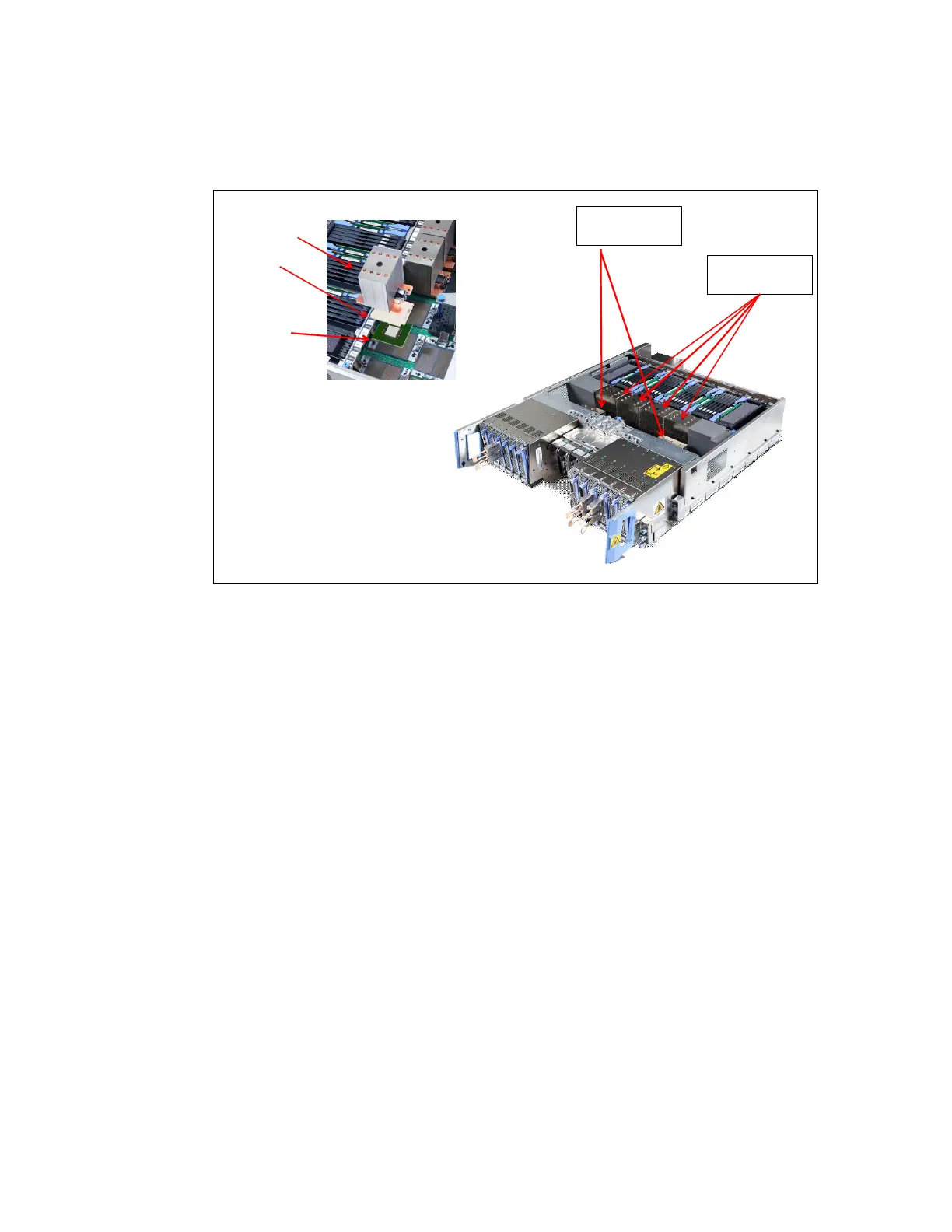
The two types of SCMs (PU and SC) are shown in Figure 2-12.
Figure 2-12 Single chip modules (PU SCM and SC SCM) N20 CPC Drawer
Both PU and SC chips use CMOS 14S0 process state-of-the-art semiconductor technology,
which is implemented with 17-layer (PU chip) or 15-layer (SC chip) copper interconnections
and Silicon-On-Insulator (SOI) technologies. The chip lithography line width is 22 nm.
The SCMs are plugged into a card that is part of the CPC drawer packaging. The
interconnectivity between the CPC drawers is accomplished through SMP connectors and
cables. One inter-drawer connection per node of the CPC drawer is used for the two drawer
Model N20 configuration. This configuration allows a multi drawer system to be displayed as a
symmetric multiprocessor (SMP) system.
Each node has three SCMs: Two PU SCMs and one SC SCM.
2.3.2 Processor unit (PU) chip
The z13s PU chip (installed as a PU SCM) is an evolution of the zBC12 core design. It uses
CMOS 14S0 technology, out-of-order instruction processing, pipeline enhancements,
dynamic simultaneous multithreading (SMT), single-instruction multiple-data (SIMD), and
redesigned, larger caches.
PU Chip
Cap
2x SC SCMs
(Air Cooled)
PU SCM
Heatsink
4x PU SCMs
(Air Cooled)
• SC SCM has similar heatsink design
but is shorter