Chapter 2. Central processor complex hardware components 79
2. Click Planning → Tools → Power Estimation Tools.
3. Specify the quantity for the features that are installed in your system.
This tool estimates the power consumption for the specified configuration. The tool does
not
verify that the specified configuration can be physically built.
2.8.6 Cooling requirements
The z13s is an air-cooled system. It requires chilled air, ideally coming from under a raised
floor, to fulfill the air cooling requirements. The chilled air is usually provided through
perforated floor tiles. The amount of chilled air that is required for various temperatures under
the floor of the computer room is indicated in the z13s Installation Manual for Physical
Planning, GC28-6953.
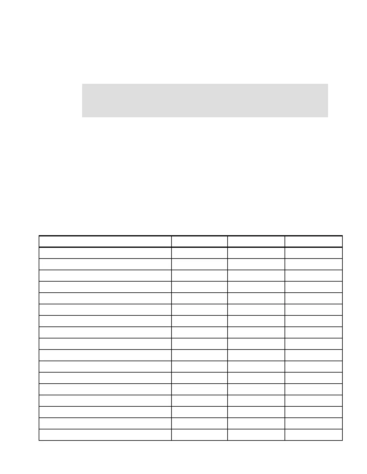
2.9 Summary of z13s structure
Table 2-14 summarizes all aspects of the z13s structure.
Table 2-14 System structure summary
Power consumption: The exact power consumption for your system will vary. The object
of the tool is to produce an
estimation of the power requirements to aid you in planning for
your system installation. Actual power consumption after installation can be confirmed on
the HMC System Activity Display.
Description Model N10 Model N20 - 1 Model N20 - 2
Number of PU SCMs 2 4 8
Number of SC SCMs 1 2 4
Total number of PUs 13 26 26
Maximum number of characterized PUs 10 20 20
Number of CPs 0 - 6 0 - 6 0-6
Number of IFLs 0 - 10 0 - 20 0-20
Number of ICFs 0 - 10 0 - 20 0-20
Number of zIIPs 0 - 6 0 - 12 0-12
Standard SAPs 2 3 3
Additional SAPs 0-2 0-3 0-3
Standard spare PUs 0 2 2
Enabled memory sizes 64 - 984 GB 64 - 2008 GB 64 - 4056 GB
L1 cache per PU 96-I / 128-D KB 96-I / 128-D KB 96-I / 128-D KB
L2 cache per PU 2-I / 2-D MB 2-I / 2-D MB 2-I / 2-D MB
L3 shared cache per PU chip 64 MB 64 MB 64 MB
L4 shared cache 480 MB 960 MB 1920 MB
Cycle time (ns) 0.233 0.233 0.233
 Loading...


