58 IBM z13s Technical Guide
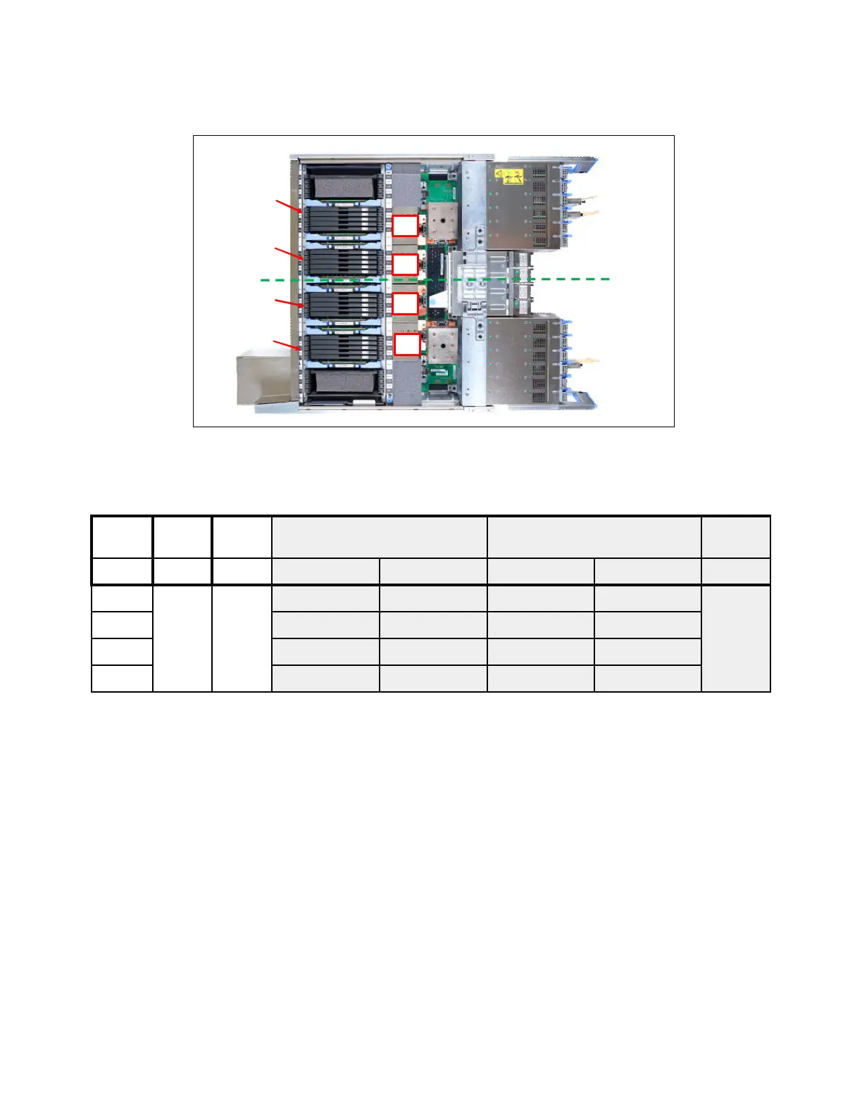
Figure 2-20 shows physical view of the N20 one CPC drawer memory DIMM plug locations
Figure 2-20 Model N20 one drawer memory plug locations
Table 2-7 shows the standard memory plug summary by node for new build systems.
Table 2-7 Model N20 single CPC drawer - physically installed memory
Memory
DIMMS
MD16-MD20
Front
NODE 0
NODE 1
Rear
Memory
DIMMS
MD21-MD25
Memory
DIMMS
MD06-MD10
Memory
DIMMS
MD11-MD15
PU
PU
PU
PU
Cust
Mem
Total
Phys
Increm
ent
Node 1
DIMM location / size GB
Node 0
DIMM location / size GB
(GB) GB GB MD06-MD10 MD11-MD15 MD16-MD20 MD21-MD25 Dial Max
64 160 8
16 16 88
72
16 16
80 16 16
88 16 16