Chapter 3. Central processor complex system design 85
The 4-level cache structure is implemented within the PU and Storage Control (SC) SCMs.
Each node of the CPC drawer has one L4 cache. The first three levels (L1, L2, and L3) are on
each PU chip (PU SCM), and L4 is on the SC SCMs:
L1 and L2 caches use static random-access memory (SRAM), and are private for each
core.
The L3 cache uses embedded dynamic SRAM (eDRAM) and is shared by all active cores
(six or seven) within the PU chip. Each node in the CPC drawer has two L3 caches. A z13s
Model N20 with two CPC drawers therefore has eight L3 caches, resulting in 512 MB (8 x
64 MB) of shared PU chip-level cache.
L4 cache also uses eDRAM, and is shared by all PU chips on the node of a CPC drawer.
Each L4 cache has 480 MB for previously owned and some L3-owned lines least recently
used (LRU) and 224 MB for a non-data inclusive coherent directory that points to L3
owned lines that have not been included in L4 cache. A z13s Model N20 with two CPC
drawers has 1920 MB (2 x 2 x 384 MB) of shared L4 cache and 896 MB (2 x 2 x 224 MB)
of NIC directory.
Main storage has up to 2.0 TB addressable memory per CPC drawer, using 20 DIMMs
(total of 5 per feature). A z13s Model N20 with two CPC drawers can have up to 4 TB of
addressable main storage.
Considerations
Cache sizes are being limited by ever-diminishing cycle times because they must respond
quickly without creating bottlenecks. Access to large caches costs more cycles. Instruction
and data cache (L1) sizes must be limited because larger distances must be traveled to reach
long cache lines. This L1 access time generally occurs in one cycle, which prevents increased
latency.
Also, the distance to remote caches as seen from the microprocessor becomes a significant
factor. An example is the L4 cache that is not on the microprocessor (and might not even be in
the same CPC drawer). Although the L4 cache is rather large, several cycles are needed to
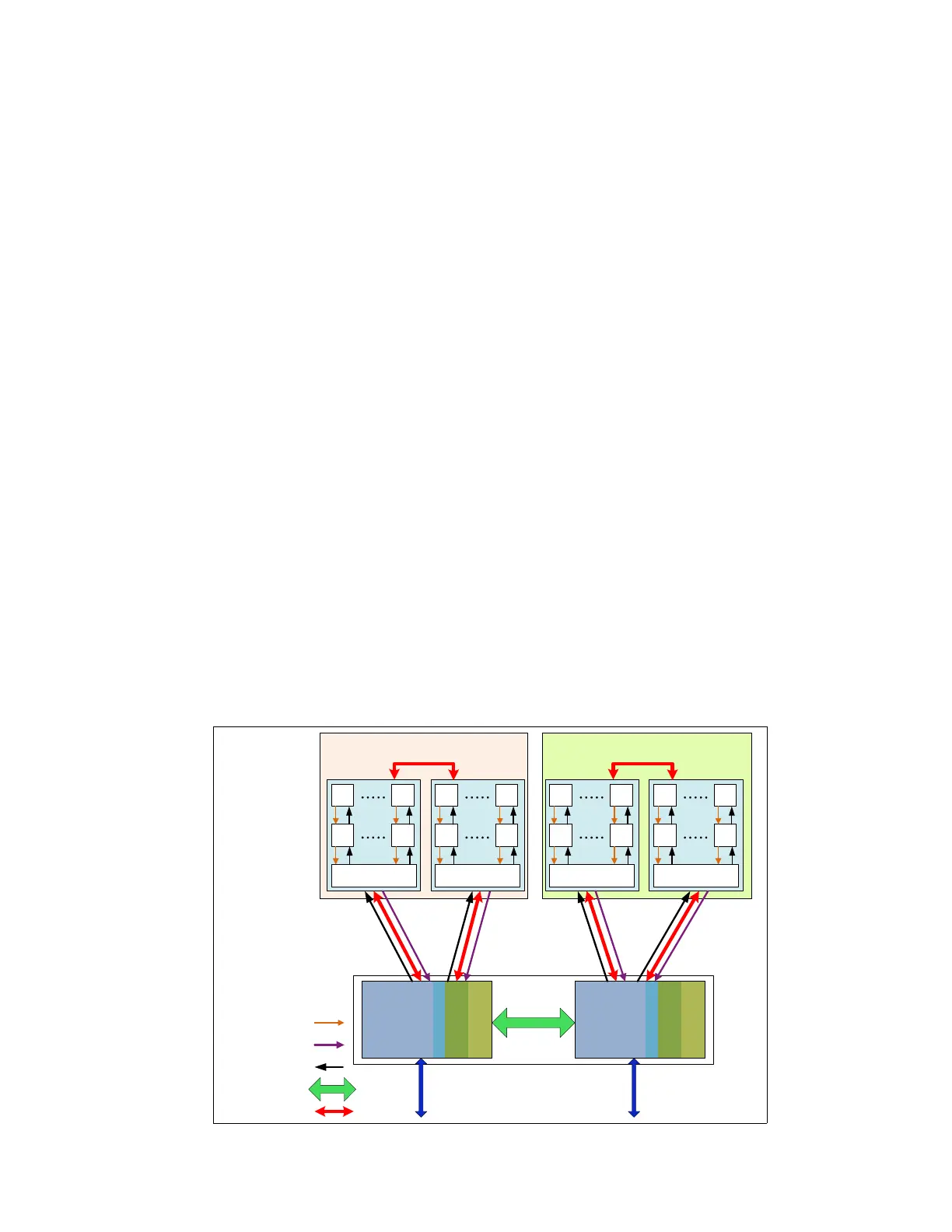
travel the distance to the cache. Figure 3-2 shows the node-cache topology of z13s servers.
Figure 3-2 z13s cache topology
Node 0Node 1
64MB eDRAM
Inclusive L3
L1
L2
2MB
L1
L2
2MB
64MB eDRAM
Inclusive L3
L1
L2
2MB
L1
L2
2MB
64MB eDRAM
Inclusive L3
L1
L2
2MB
L1
L2
2MB
64MB eDRAM
Inclusive L3
L1
L2
2MB
L1
L2
2MB
480MB
eDRAM
L4
224MB
eDRAM
NIC
L3
owned
lines
480MB
eDRAM
L4
224MB
eDRAM
NIC
L3
owned
lines
CP Stores
LRU Cast-out
Data Fetch Return
S-Bus
X-Bus
To other CPC drawer
PU chip (7 cores) PU chip (6 cores) PU chip (6 cores) PU chip (7 cores)
 Loading...