IDEC SmartRelay functions
IDEC SmartRelay Manual 191
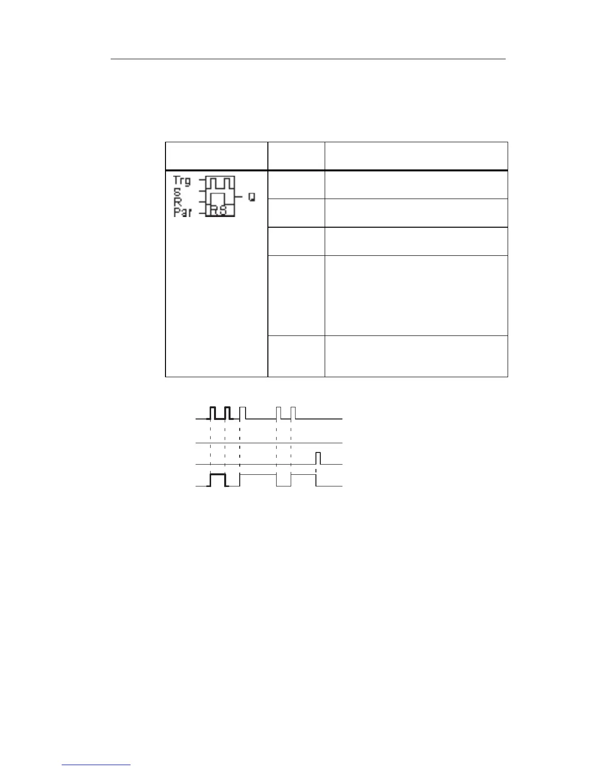
4.4.22 Current impulse relay
Short description
A short pulse at the input sets and resets the output.
The bold printed section of
the timing diagram is also
shown in the symbol for the
current impulse relay.
Timing diagram
Functional description
Output Q changes its status; that is, the outpu
t is set or reset
with each 0 to 1 transition at input Trg and if the inputs S and
R = 0.
The signal at input Trg does not influence the special
function when
S or R = 1.
You set the current impulse relay with a signal at input S.
The output is set hi.
You
reset the current impulse relay with a signal at input R.
The output is set lo.
Symbol in IDEC
SmartRelay
Wiring Description
Input Trg You set and reset output Q with a
signal at input Trg (Trigger).
Input S You set output Q with a signal at input
S.
Input R You reset output Q with a signal at
input R.
Parameter Selection:
RS (R input priority) or
SR (S input priority)
Retentivity:
/ = No retentivity
R = The status is retentive.
Output Q Q is set with a signal at Trg, and reset
with the next signal at Trg, if S and R =
0.